


Mikroelektronika d.o.o.
ADC 11 Click Board™
ADC 11 Click Board™
SKU: MIKROE-4593
Couldn't load pickup availability


Key Features
Overview
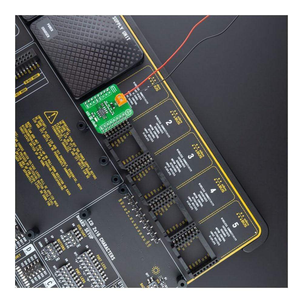
The ADC 11 Click Board™ is a compact add-on board that contains a high-performance data converter. This board features the LTC1864, a 16-bit 250ksps analogue-to-digital converter from Analog Devices. With a typical supply current only 850µA at the maximum sampling frequency, the LTC1864 is among the lowest power consumption ADCs available. After conversion, the LTC1864 goes into a low-power Sleep mode, further reducing the supply current. That’s why it can run at proper micro-power levels in applications that do not require the maximum sampling rate of the LTC1864. This Click Board™ is suitable for high-speed data acquisition, low power battery-operated instrumentation, isolated and remote data acquisition, and many other applications.
The ADC 11 Click Board™ is supported by a mikroSDK compliant library, which includes functions that simplify software development. This Click Board™ comes as a fully tested product, ready to be used on a system equipped with the mikroBUS™ socket.
Downloads
How Does The ADC 11 Click Board™ Work?
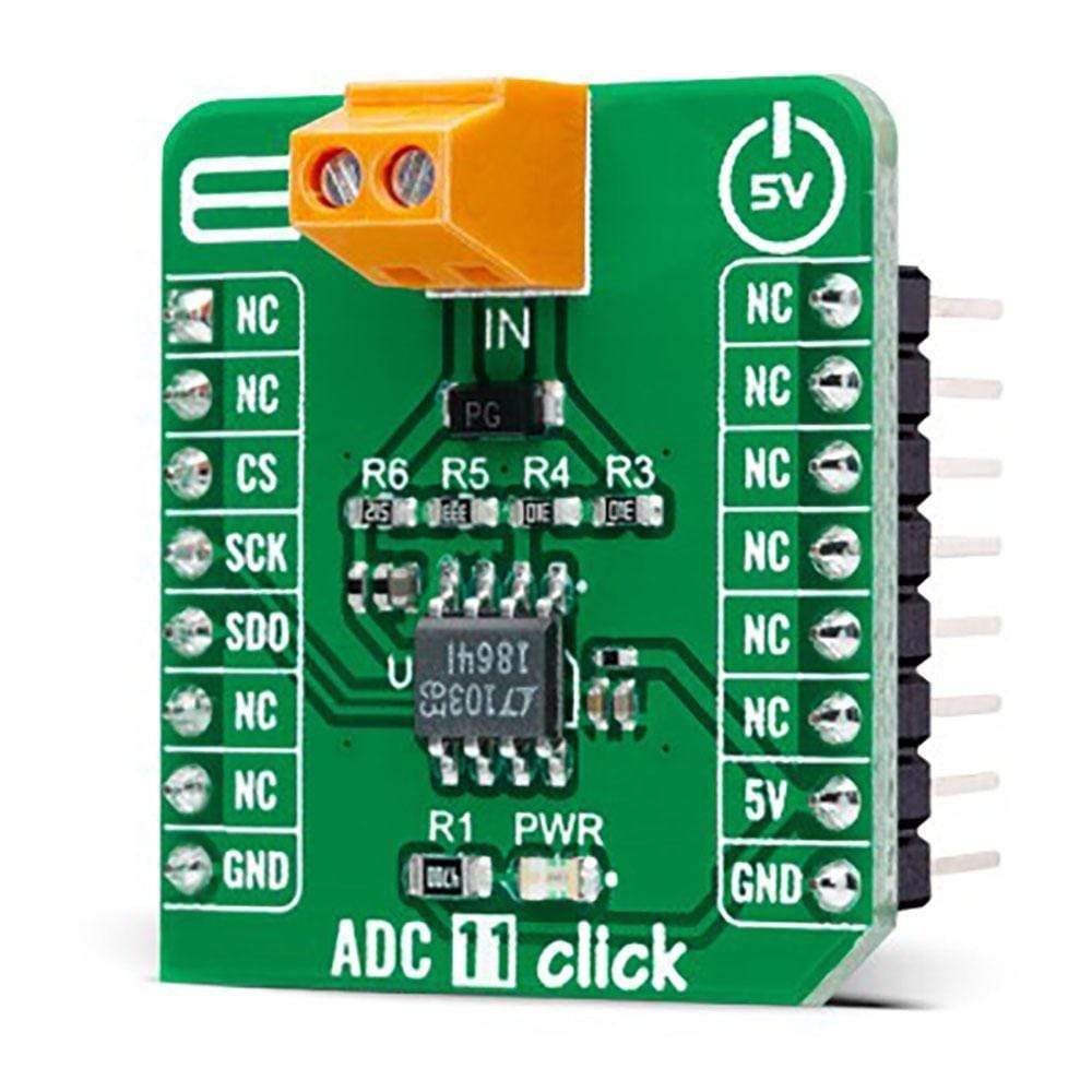
The ADC 11 Click Board™ as its foundation uses the LTC1864, a 16-bit successive approximation A/D converter with a sample-and-hold feature that operates on a single 5V supply from Analog Devices. The supply current, which can be the only 850μA at 250ksps, drops at lower speeds because the LTC1864 automatically power-down between conversions. The high impedance analog input and the ability to operate with reduced spans down to 1V full scale allow direct connection to signal sources in many applications, eliminating the need for external gain stages. Equipped with the 3-wire SPI serial interface and extremely high sample rate-to-power ratio, this Click board™ represents an ideal solution for compact, low power, high-speed systems.

The ADC 11 Click Board™ communicates with MCU through the simple 3-wire serial I/O compatible with industry-standard SPI interface. The LTC1864 has an internal conversion clock so that the clock rate does not affect the conversion. This fact allows the clock rate to run to 20MHz without concern for sample-and-hold droop at low clock frequencies or clocking the ADC too fast at high clock frequencies. The data transfer requires only 16 clock cycles which minimize the amount of time necessary to transfer the data. The entire conversion can be transferred in only 800ns if the conversion clock runs at the maximum rate of 20MHz.
The ADC 11 Click Board™ operates only with a 5V logic voltage level. The board must perform appropriate logic voltage level conversion before use with MCUs with different logic levels. However, the Click board™ comes equipped with a library containing functions and an example code that can be used, as a reference, for further development.
SPECIFICATIONS
| Type | ADC |
| Applications | Can be used for high-speed data acquisition, low power battery-operated instrumentation, isolated and remote data acquisition, and many other applications. |
| On-board modules | LTC1864 - 16-bit successive approximation A/D converter with a sample-and-hold feature that operates on a single 5V supply from Analog Devices |
| Key Features | One channel 16bit 250ksps ADC, singl 5V supply, low supply current, auto-shutdown feature, SPI compatible interface, and more. |
| Interface | SPI |
| Compatibility | mikroBUS |
| Click board size | S (28.6 x 25.4 mm) |
| Input Voltage | 5V |
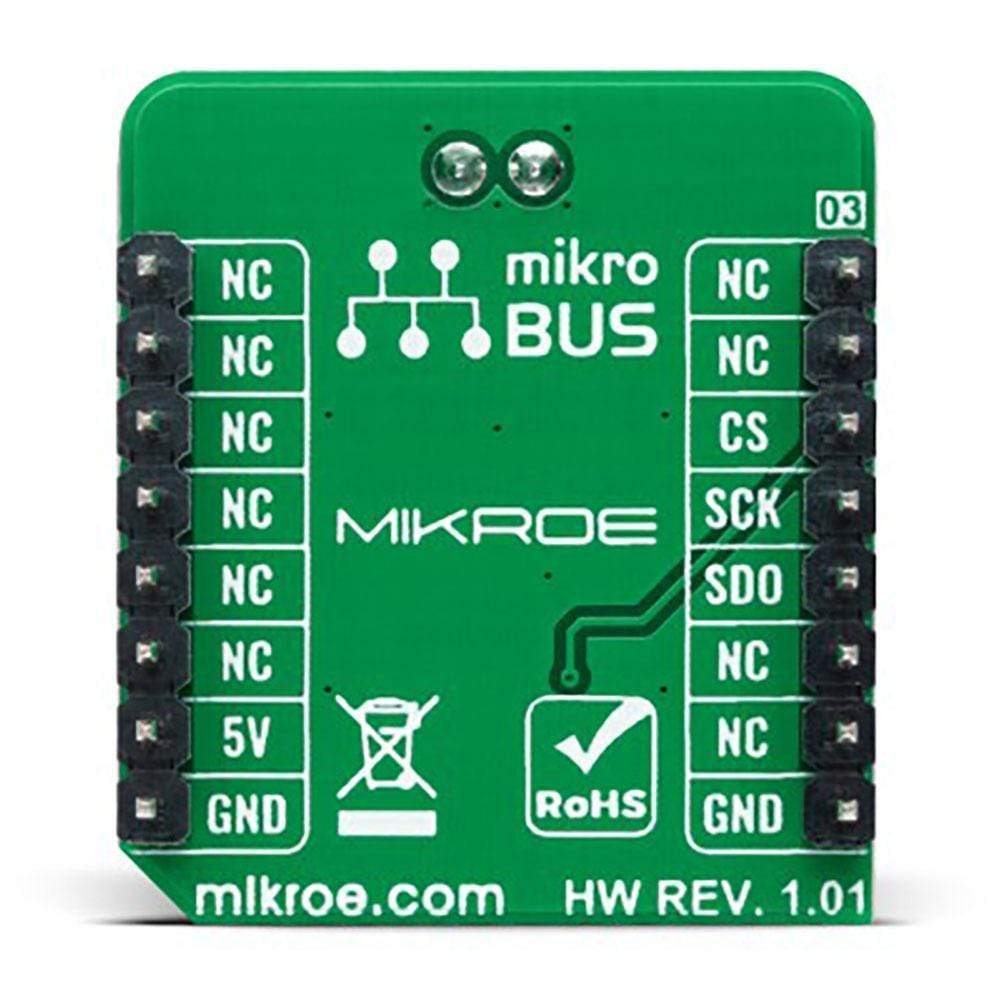
PINOUT DIAGRAM
This table shows how the pinout on the ADC 11 Click Board™ corresponds to the pinout on the mikroBUS™ socket (the latter shown in the two middle columns).
| Notes | Pin | Pin | Notes | ||||
|---|---|---|---|---|---|---|---|
| NC | 1 | AN | PWM | 16 | NC | ||
| NC | 2 | RST | INT | 15 | NC | ||
| SPI Chip Select | CS | 3 | CS | RX | 14 | NC | |
| SPI Clock | SCK | 4 | SCK | TX | 13 | NC | |
| SPI Data OUT | SDO | 5 | MISO | SCL | 12 | NC | |
| NC | 6 | MOSI | SDA | 11 | NC | ||
| NC | 7 | 3.3V | 5V | 10 | 5V | Power Supply | |
| Ground | GND | 8 | GND | GND | 9 | GND | Ground |
ONBOARD SETTINGS AND INDICATORS
| Label | Name | Default | Description |
|---|---|---|---|
| LD1 | PWR | - | Power LED Indicator |
ADC 11 CLICK ELECTRICAL SPECIFICATIONS
| Description | Min | Typ | Max | Unit |
|---|---|---|---|---|
| Supply Voltage | - | 5 | - | V |
| Analog Input Supply Voltage | 0 | - | 5 | V |
| Resolution | 16 | - | - | bits |
| Sampling Rate | - | - | 250 | ksps |
| Operating Temperature Range | -40 | +25 | +85 | °C |
| General Information | |
|---|---|
Part Number (SKU) |
MIKROE-4593
|
Manufacturer |
|
| Physical and Mechanical | |
Weight |
0.02 kg
|
| Other | |
EAN |
8606027382482
|
Frequently Asked Questions
Have a Question?
Be the first to ask a question about this.