


Mikroelektronika d.o.o.
ATA6571 Click Board™
ATA6571 Click Board™
SKU: MIKROE-4381
Couldn't load pickup availability


Key Features
Overview
The ATA6571 Click Board™ is a compact add-on board containing a transceiver for high-speed CAN applications. This board features the ATA6571, a standalone high-speed CAN FD transceiver that interfaces a CAN protocol controller and the physical two-wire CAN bus from Microchip. It offers several operating modes with diagnostic and fail-safe features that enhance system reliability. Its advanced low-power management with local and remote Wake-Up support makes it possible to achieve low current consumption in Standby and Sleep mode. This Click Board™ is suitable for all types of high-speed CAN networks, especially in nodes requiring low-power mode with wake-up capability via the CAN bus.
The ATA6571 Click Board™ is supported by a mikroSDK compliant library, which includes functions that simplify software development. This Click Board™ comes as a thoroughly tested product, ready to be used on a system equipped with the mikroBUS™ socket.
Downloads
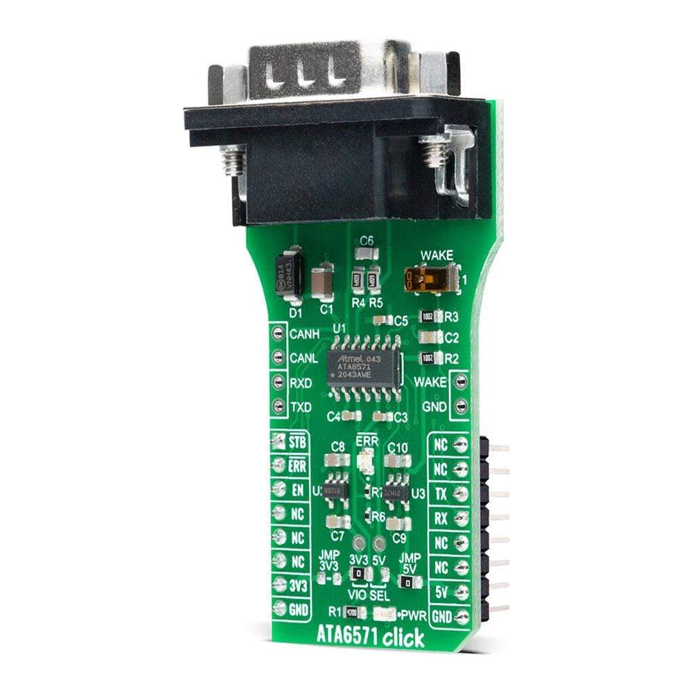
How Does The ATA6571 Click Board™ Work?
The ATA6571 Click Board™ is based on the ATA6571, a standalone high-speed CAN FD transceiver up to 5 Mbit/s that interfaces a Controller Area Network (CAN) protocol controller and the physical two-wire CAN bus from Microchip. It offers improved Electromagnetic Compatibility (EMC) and ESD performance. Its advanced low-power management with local and remote Wake-Up support makes it possible to achieve low current consumption in Standby and Sleep mode, even when the internal I/O and transceiver supplies are switched off. The ATA6571 supports functional safety-related applications. Internal Safety Mechanisms prevent device malfunction due to under-voltage and overtemperature, detect bus dominant and recessive clamping, and prevent blocking of the CAN bus due to permanent dominant or recessive states of RXD and TXD.

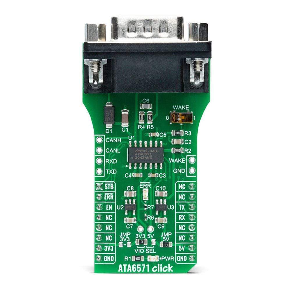
The ATA6571 has one pin used for waking up the device from Sleep mode. This pin is connected to an external switch labelled as WAKE to generate a local Wake-Up function. A Wake-Up event on the CAN bus switches the inhibit output pin INH to the High level. The INH pin provides an internal switch towards the battery supply voltage and control external voltage regulators, the MCP1804 from Microchip. Through SMD jumpers labelled as JMP3V3 and JMP5V, the LDOs output voltages can be used to power up the mikroBUS™ 3.3V and 5V power rails. However, it should be noted that Mikroe does not advise powering up their systems this way. That is why these jumpers are left unpopulated by default.
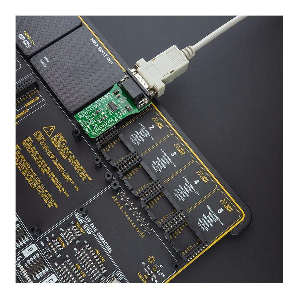
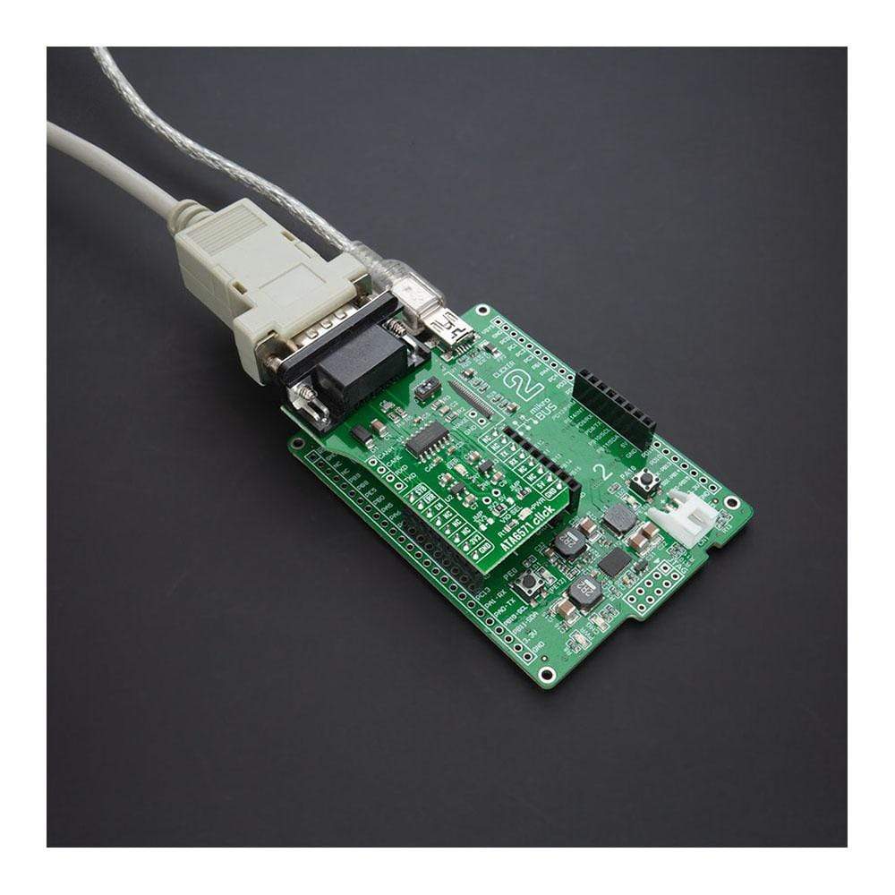
The ATA6571 communicates with MCU using the UART interface with the default baud rate of 9600 bps for the data transfer. In addition to UART communication pins from the mikroBUS™ socket, the user can connect the TX/RX signals directly through the UART External header on the left edge of the board. This Click board™ comes equipped with the standard DB-9 connector, making interfacing with the CAN bus simple and easy. Besides, the user can connect the CAN signals directly through the CAN External header, also on the left edge of the board.
In addition to these features, the ATA6571 also uses several GPIO pins connected to the mikroBUS™ socket. The EN pin routed on the CS pin of the mikroBUS™ is used for Enable Control. Together with the STB pin routed on the AN pin of the mikroBUS™ socket, which represents Standby Mode Control, the EN pin controls the operating mode of the device. It also provides a pull-down to force the transceiver into Recessive mode if EN is disconnected. Next to these pins, the ATA6571 uses another pin labelled as ERR routed on the RST pin of the mikroBUS™ used as Error Indication. This pin reflects the device status and can be visually displayed using the LED indicator labelled as ERR.
The ATA6571 Click Board™ is designed to operate with both 3.3V and 5V logic voltage levels selected via the VIO SEL jumper. It allows for both 3.3V and 5V capable MCUs to use the UART communication lines properly. However, the Click board™ comes equipped with a library that contains easy to use functions and an example code that can be used, as a reference, for further development.
SPECIFICATIONS
| Type | CAN |
| Applications | Can be used for all types of high-speed CAN networks, especially in nodes requiring low-power mode with wake-up capability via the CAN bus. |
| On-board modules | Thew ATA6571 Click Board™ is based on the ATA6571, a standalone high-speed CAN FD transceiver up to 5 Mbit/s that interfaces a Controller Area Network (CAN) protocol controller and the physical two-wire CAN bus from Microchip. |
| Key Features | High-Speed CAN Transceiver, improved EMC Compatibility and ESD performance, very low power consumption, remote wake-up support, protection and diagnostic functions, and more. |
| Interface | UART |
| Compatibility | mikroBUS |
| Click board size | L (57.15 x 25.4 mm) |
| Input Voltage | 3.3V or 5V,External |
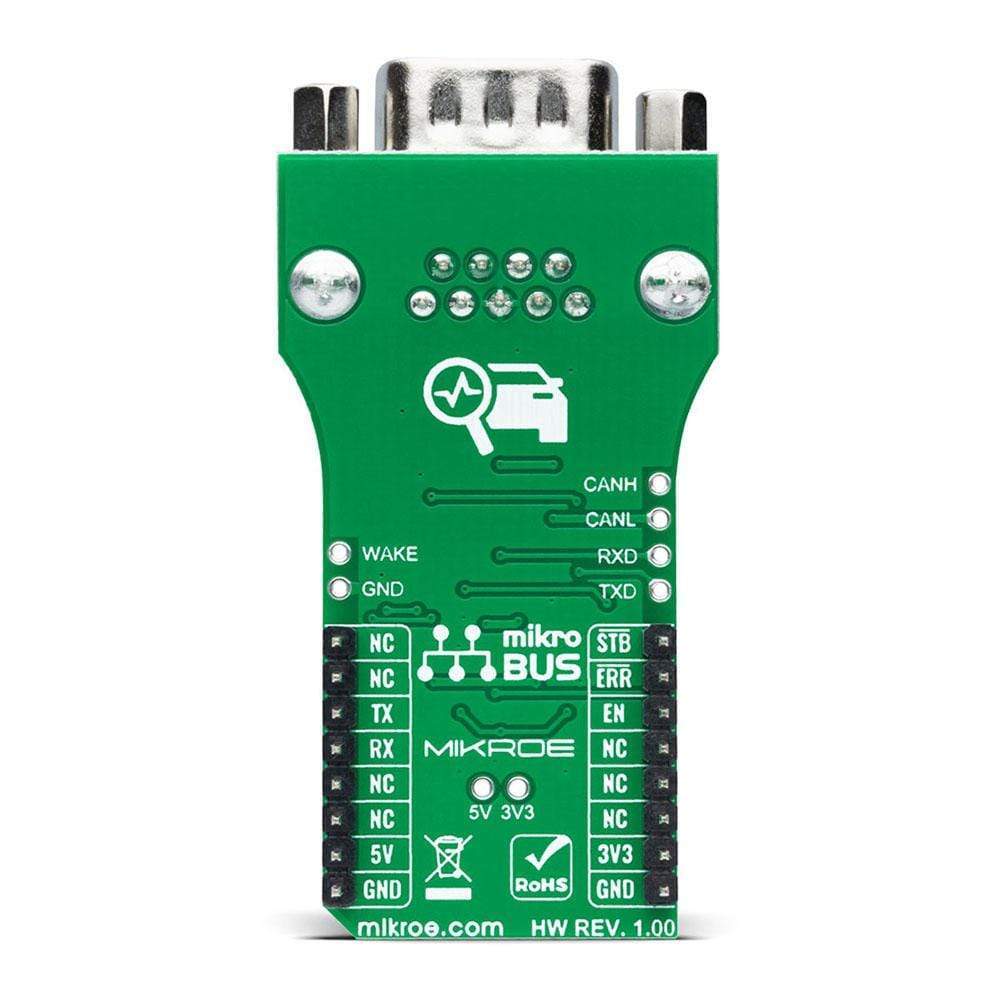
PINOUT DIAGRAM
This table shows how the pinout of the ATA6571 Click Board™ corresponds to the pinout on the mikroBUS™ socket (the latter shown in the two middle columns).
| Notes | Pin | Pin | Notes | ||||
|---|---|---|---|---|---|---|---|
| Standby Mode Control | STB | 1 | AN | PWM | 16 | NC | |
| Error Indication | ERR | 2 | RST | INT | 15 | NC | |
| Enable Control | EN | 3 | CS | RX | 14 | RX | UART RX |
| NC | 4 | SCK | TX | 13 | TX | UART TX | |
| NC | 5 | MISO | SCL | 12 | NC | ||
| NC | 6 | MOSI | SDA | 11 | NC | ||
| Power Supply | 3.3V | 7 | 3.3V | 5V | 10 | 5V | Power Supply |
| Ground | GND | 8 | GND | GND | 9 | GND | Ground |
ONBOARD SETTINGS AND INDICATORS
| Label | Name | Default | Description |
|---|---|---|---|
| LD1 | PWR | - | Power LED Indicator |
| LD2 | ERR | - | Error LED Indicator |
| JP1 | VIO SEL | Left | Power Supply Voltage Selection 3V3/5V: Left position 3V3, Right position 5V |
| JMPR1-JMPR2 | JMP3V3-JMP5V | JMP5V Populated | 3V3/5V LDO Jumpers |
| SW1 | WAKE | Down | Wake-Up Switch |
ATA6571 CLICK ELECTRICAL SPECIFICATIONS
| Description | Min | Typ | Max | Unit |
|---|---|---|---|---|
| Supply Voltage VIO | -0.3 | - | 5.5 | V |
| Battery Supply Voltage | 4.5 | - | 28 | V |
| Communication Data Rates | - | - | 5 | Mbit/s |
| Voltage between CANH and CANL pins | -27 | - | +42 | V |
| Operating Temperature Range | -40 | - | +150 | °C |
| General Information | |
|---|---|
Part Number (SKU) |
MIKROE-4381
|
Manufacturer |
|
| Physical and Mechanical | |
Weight |
0.027 kg
|
| Other | |
EAN |
8606027381386
|
Frequently Asked Questions
Have a Question?
Be the first to ask a question about this.