


Mikroelektronika d.o.o.
RTD 2 Click Board™
RTD 2 Click Board™
SKU: MIKROE-4282
Couldn't load pickup availability


Overview
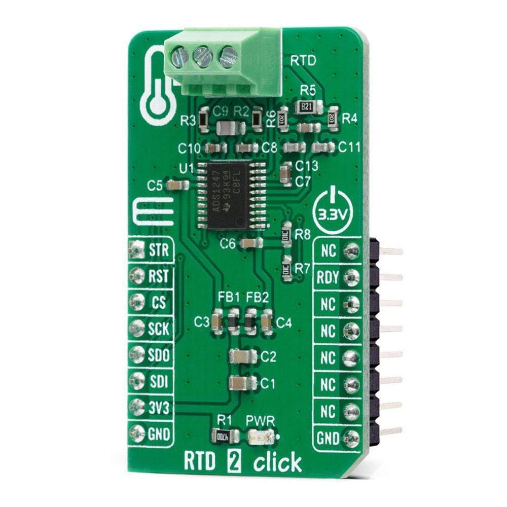
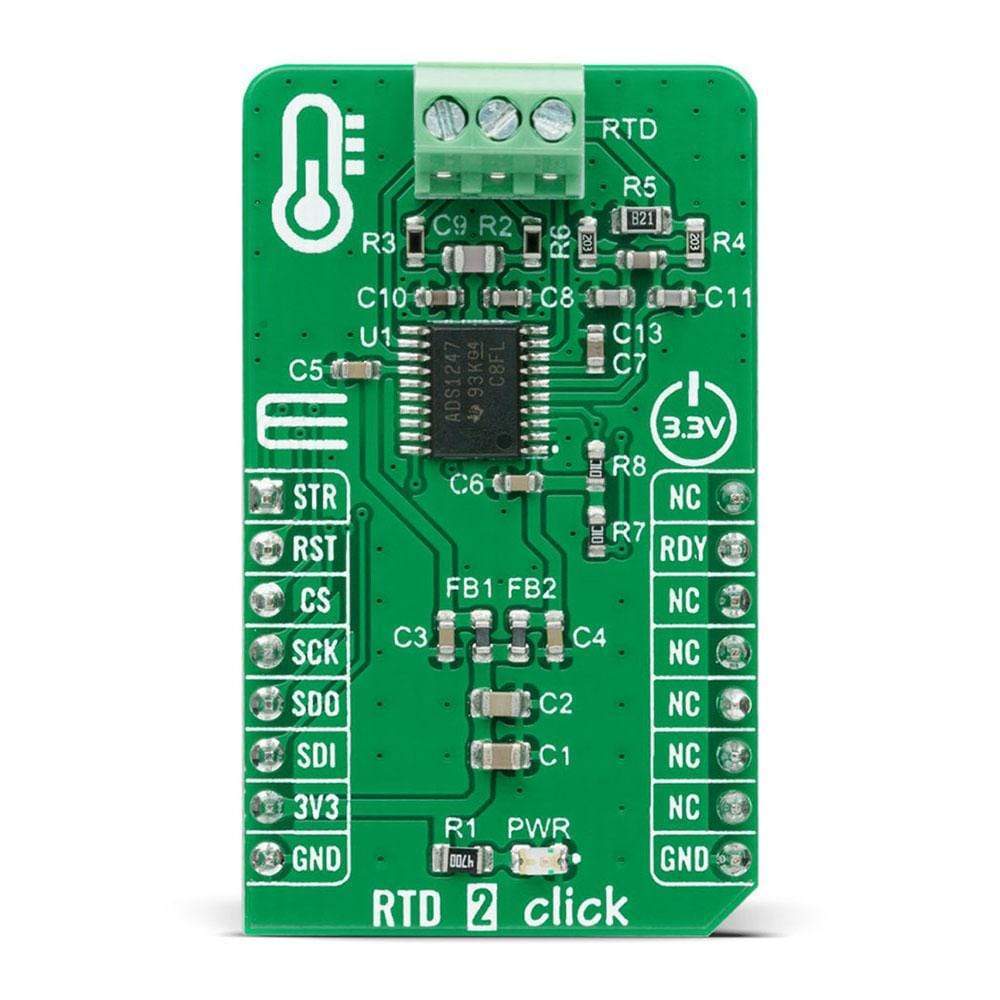
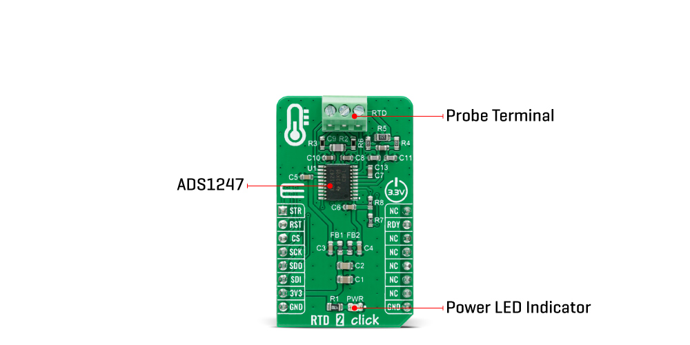
The RTD 2 Click Board™ is a compact add-on board used for applications with resistive elements that change resistance over temperature. This board features the ADS1247, 24-bit analogue-to-digital converter with a programmable gain amplifier (PGA) for sensor measurement applications from Texas Instruments. It features a precision delta-sigma (ΔΣ) ADC with a single-cycle settling digital filter, and an internal oscillator, but also provides a low-drift voltage reference, and two matched programmable excitation current sources (IDACs). It also integrates sensor burn-out detection, voltage bias for thermocouples, system monitoring, and digital GPIOs. This Click Board™ is suitable for temperature sensor measurements such as RTDs, thermocouples and thermistors, for pressure measurements, process control, and many more.
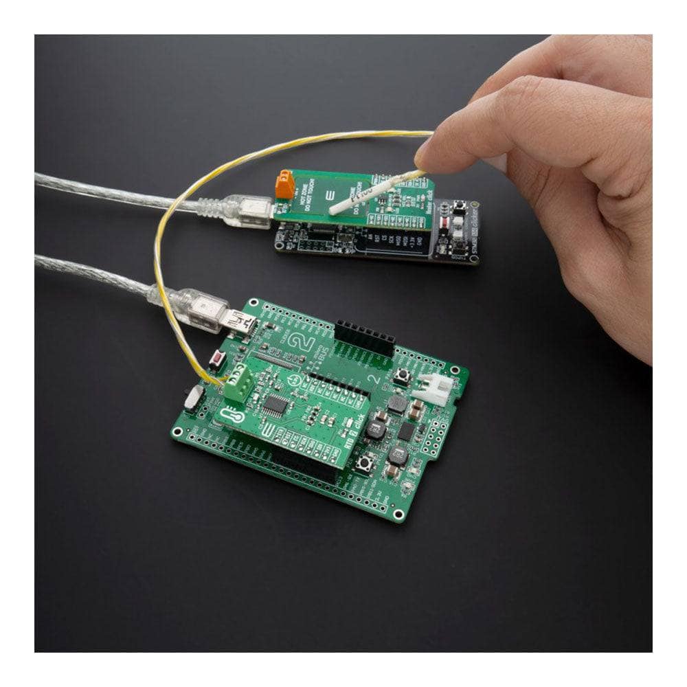
The RTD 2 Click Board™ is supported by a mikroSDK compliant library, which includes functions that simplify software development. This Click Board™ comes as a fully tested product, ready to be used on a system equipped with the mikroBUS™ socket
Downloads
How Does The RTD 2 Click Board™ Work?
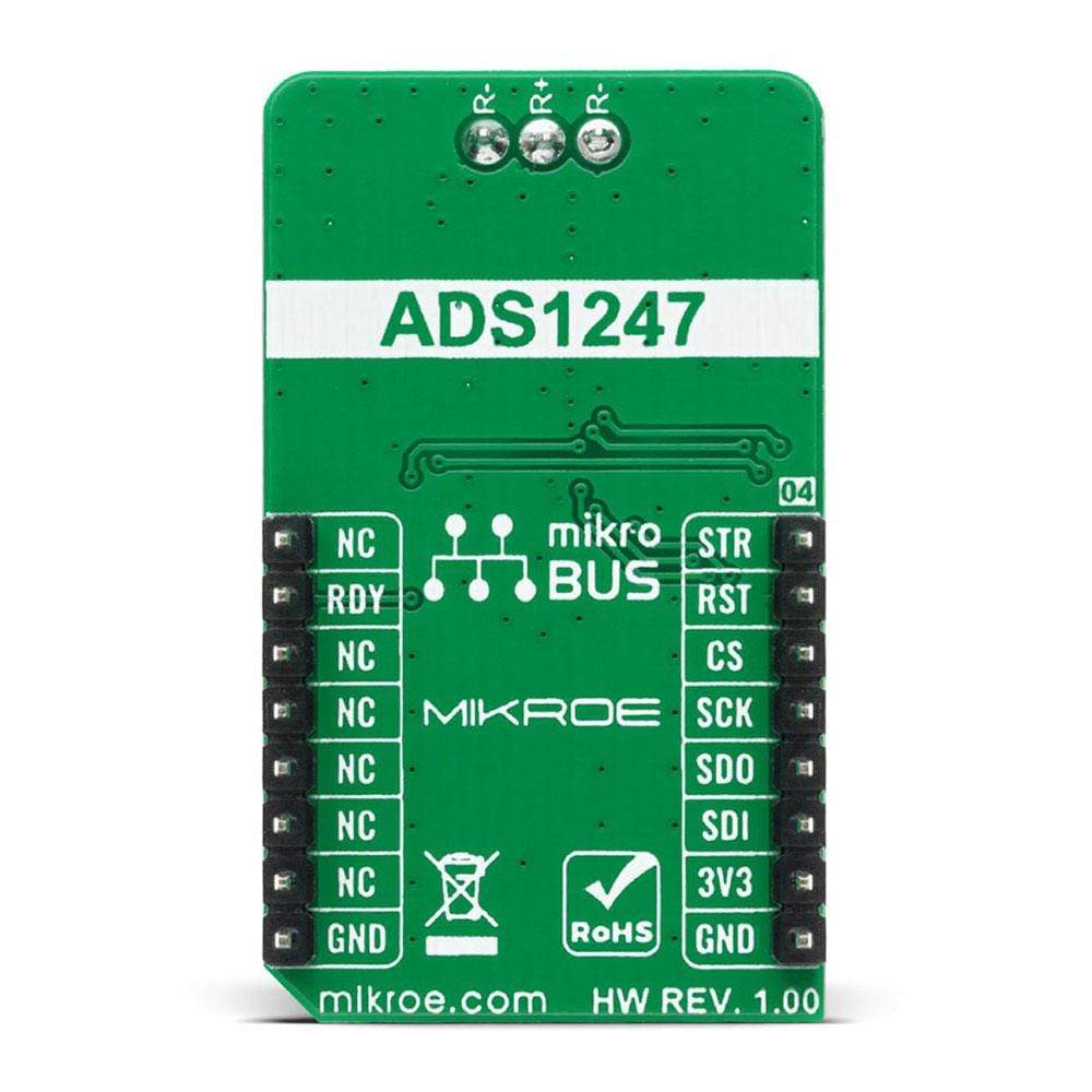
The RTD 2 Click Board™ is based on the ADS1247, a highly integrated 24-bit data converters with a programmable gain amplifier (PGA) for sensor measurement applications from Texas Instruments. The ADS1247 includes a delta-sigma (ΔΣ) ADC with an adjustable single-cycle settling digital filter, an internal oscillator, and an SPI-compatible serial interface. It also has a flexible input multiplexer with system monitoring capability and general-purpose I/O settings, a very low-drift voltage reference, and two matched current sources for sensor excitation. The ADS1247 provides a system monitor function. This function can measure the analog power supply, digital power supply, external voltage reference, or ambient temperature. Note that the system monitor function provides a coarse result. When the system monitor is enabled, the analog inputs are disconnected.
The two IDAC current sources integrated in the ADS1247 are used to implement the lead-wire compensation. One IDAC current source (IDAC1) provides excitation to the RTD element. The other current source (IDAC2) has the same current setting, providing cancellation of lead-wire resistance by generating a voltage drop across lead-wire resistance R2 equal to the voltage drop across R1 resistor (9.09k). Because the voltage across the RTD is measured differentially at ADC pins AIN1 and AIN2 of the ADS1247, the voltages across the lead-wire resistances cancel. The ADC reference voltage (pins REFP0 and REFN0) is derived from the voltage across R5 resistor with the currents from IDAC1 and IDAC2, providing ratiometric cancellation of current-source drift. R5 also level shifts the RTD signal to within the ADC specified common-mode input range.
The RTD 2 Click Board™ communicates with MCU using the standard SPI serial interface with additional data ready signal routed on the INT pin of the mikroBUS™ socket labelled as RDY. Data Ready signal is used to indicate when a new conversion is complete, and the conversion result is stored in the conversion result buffer. It also has an active-low Reset signal routed on the RST pin of the mikroBUS™ used to reset the device, and precise conversion control signal routed on the AN pin of the mikroBUS™ socket labelled as STR. The ADS1247 stays in Reset Mode as long as the RST pin stays low. When the RST pin goes high, the ADC comes out of Reset Mode and can convert data.
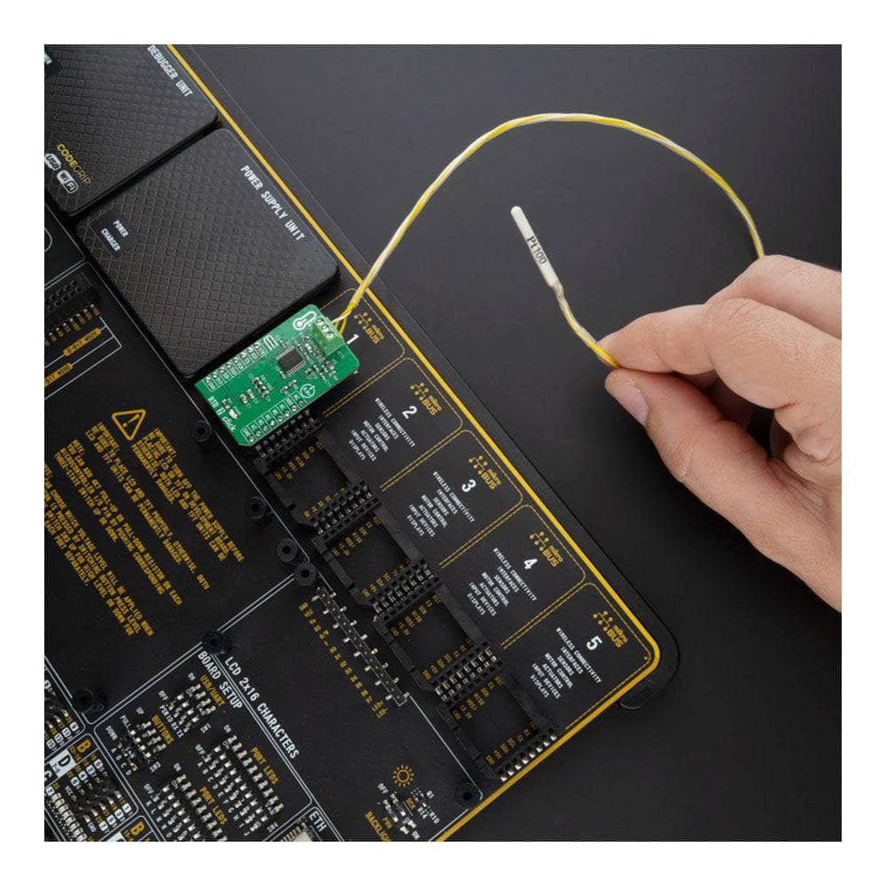
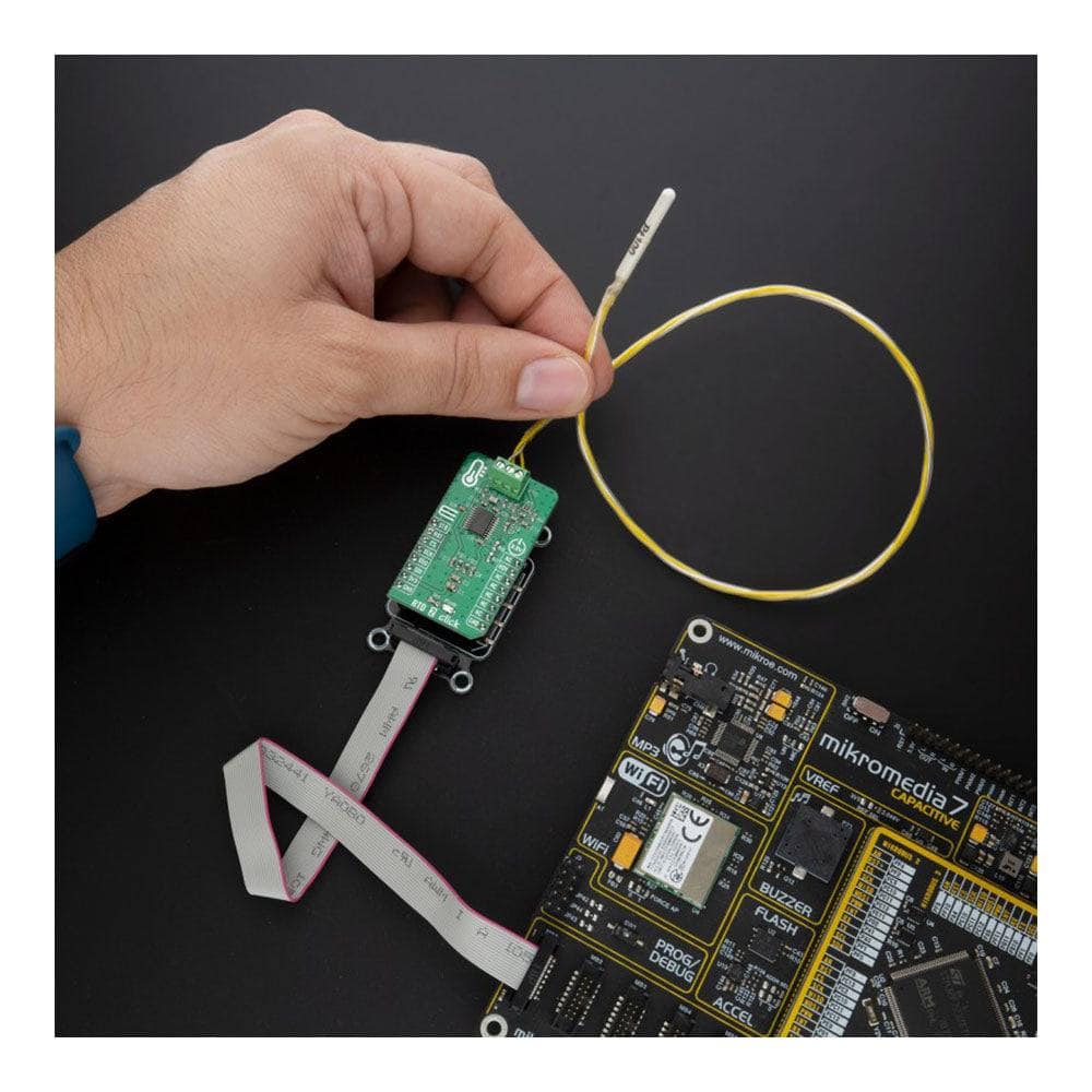
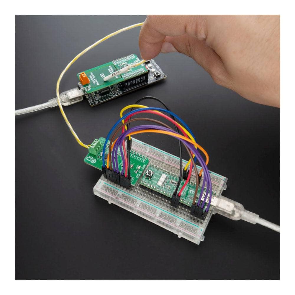
The RTD 2 Click Board™ can work only with 3-wire probe types that MikroE has in its offer such as the PT100 type Platinum Probe, a type of RTD probe used to measure temperatures up to 250°C. Platinum is an excellent choice since they are very stable and reusable, and are resistant to corrosion or oxidation. The measurement probe is connected to the RTD 2 Click by using the screw terminal on the top of the board, and it has wires that can be 1m long, which makes it possible to measure high temperatures from a safe distance.
The RTD 2 Click Board™ is designed to be operated only with a 3.3V logic voltage level. A proper logic voltage level conversion should be performed before the Click board™ is used with MCUs with different logic levels. However, the Click board™ comes equipped with a library that contains easy to use functions and an example code that can be used as a reference for further development.
SPECIFICATIONS
| Type | Temperature & humidity |
| Applications | Can be used for temperature sensor measurements such as RTDs, thermocouples, and thermistors, for pressure measurements, flow meters, factory automation, and process control, and many more. |
| On-board modules | The RTD 2 Click Board™ is based on the ADS1247, a highly integrated 24-bit data converters with a programmable gain amplifier (PGA) for sensor measurement applications from Texas Instruments. |
| Key Features | Programmable Data Rates, 50/60 Hz rejection, excitation current sources (iDACs), GPIO, PGA, internal temperature sensor, self and system calibration, and more. |
| Interface | SPI |
| Compatibility | mikroBUS |
| Click board size | M (42.9 x 25.4 mm) |
| Input Voltage | 3.3V |
PINOUT DIAGRAM
This table shows how the pinout of the RTD 2 Click Board™ corresponds to the pinout on the mikroBUS™ socket (the latter shown in the two middle columns).
| Notes | Pin | Pin | Notes | ||||
|---|---|---|---|---|---|---|---|
| Conversion Start | STR | 1 | AN | PWM | 16 | NC | |
| Reset | RST | 2 | RST | INT | 15 | RDY | Data-Ready |
| SPI Chip Select | CS | 3 | CS | RX | 14 | NC | |
| SPI Clock | SCK | 4 | SCK | TX | 13 | NC | |
| SPI Data OUT | SDO | 5 | MISO | SCL | 12 | NC | |
| SPI Data IN | SDI | 6 | MOSI | SDA | 11 | NC | |
| Power Supply | 3.3V | 7 | 3.3V | 5V | 10 | NC | |
| Ground | GND | 8 | GND | GND | 9 | GND | Ground |
ONBOARD SETTINGS AND INDICATORS
| Label | Name | Default | Description |
|---|---|---|---|
| LD1 | PWR | - | Power LED Indicator |
RTD 2 CLICK ELECTRICAL SPECIFICATIONS
| Description | Min | Typ | Max | Unit |
|---|---|---|---|---|
| Supply Voltage | -0.3 | 3.3 | 5.5 | V |
| Power Consumption | - | 2.3 | - | mW |
| Sample Rate | - | - | 2 | kSPS |
| Resolution | - | 24 | - | bit |
| Operating Temperature Range | -40 | - | +105 | °C |
| General Information | |
|---|---|
Part Number (SKU) |
MIKROE-4282
|
Manufacturer |
|
| Physical and Mechanical | |
Weight |
0.019 kg
|
| Other | |
EAN |
8606027380624
|
Frequently Asked Questions
Have a Question?
Be the first to ask a question about this.