


Mikroelektronika d.o.o.
PWR Meter 2 Click Board™
PWR Meter 2 Click Board™
SKU: MIKROE-3150
Couldn't load pickup availability
Overview
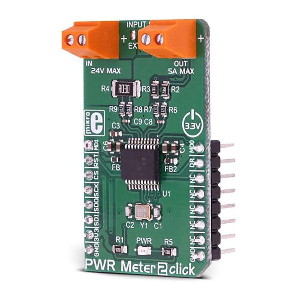
The PWR Meter 2 Click Board™ is a compact and accurate power monitoring Click Board™, capable of measuring and monitoring voltage up to 24V and current up to 5A. It carries the MCP3910, an integrated Analog Front End (AFE) device, which consists of two delta-sigma A/D Converters (ADC), two Programmable Gain Amplifiers (PGA), phase delay compensation section, voltage reference section, digital offset and gain error calibration registers, and industry-standard SPI interface. This device allows to build power monitoring device with a reasonably low count of elements: A current sensing resistor connected to one channel with the voltage divider connected to the second channel is all that it is required to perform an accurate power measurement.
Downloads
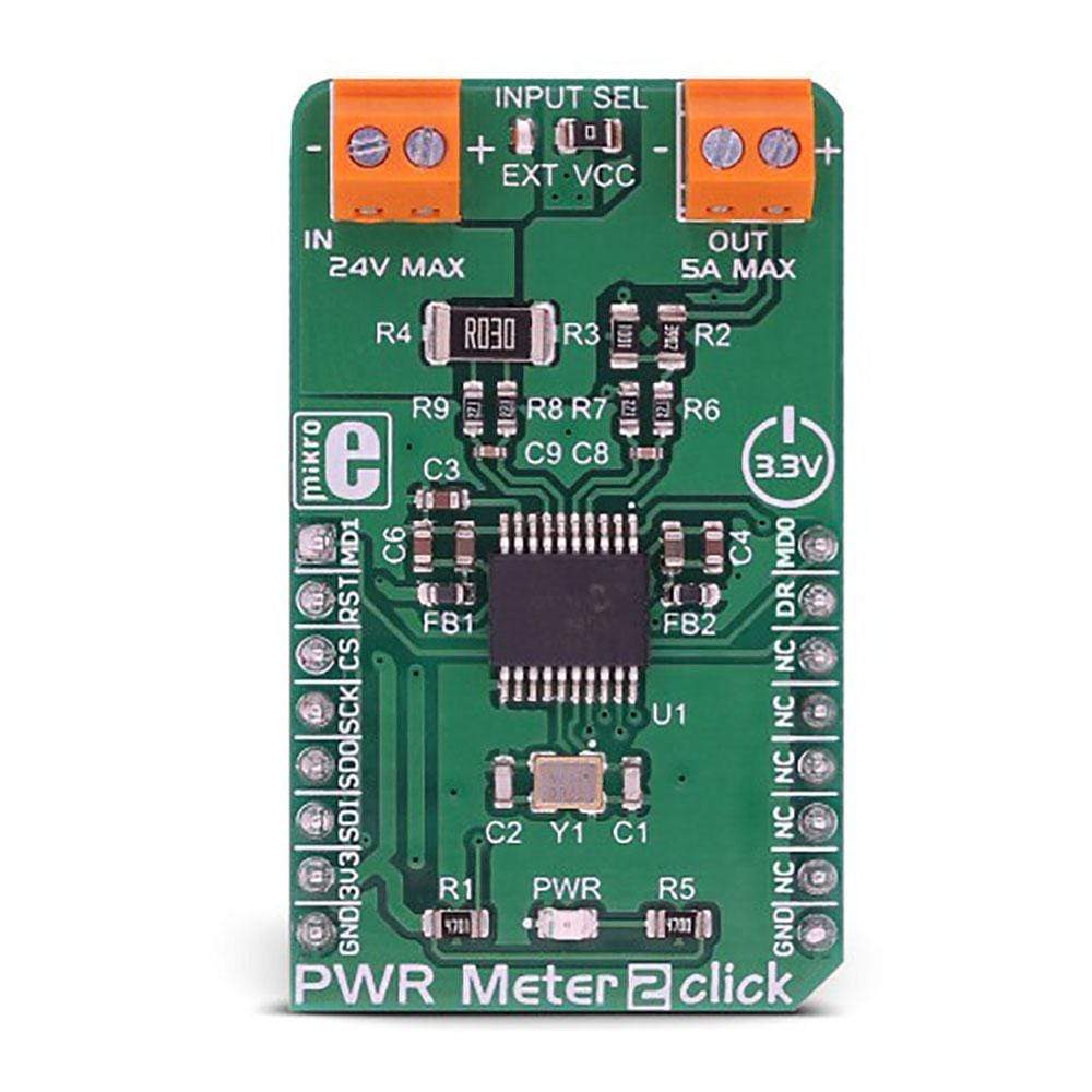
The PWR Meter 2 Click Board™ comes with two screw terminals, allowing the external circuit to be easily connected. Besides measuring the properties of an externally connected circuit, the PWR Meter 2 Click Board™click can be used to measure the power consumption of the Click board™ itself, when developing accurate power consumption monitoring applications. A shunt resistor of only 0.03 Ω offers almost no interferences with the current passing through the load, making this Click board™ applicable in a wide range of monitoring projects, such as power metering in portable and automotive devices, embedded electronic applications, power monitoring for computer peripherals, and similar applications.
How Does The PWR Meter 2 Click Board™ Work?
The PWR Meter 2 Click Board™ is equipped with the MCP3910, an integrated two-channel analog front-end (AFE) device from Microchip. This IC is composed of several sections, aimed at accurate capturing of the input voltage. Two sigma-delta input A/D converters used with the internal reference voltage of 1.2V with very low thermal drift, reducing the measurement noise at a minimum, yielding Signal to Noise ratio (SNR) up to 96dB. The input ADCs are fully configurable and can be set to work in 16-bit or 24-bit mode, can use oversampling ratio from 32 X up to 4096 X, gain ratio from 1 X to 32 X, and 24-bit digital offset and gain error correction for each ADC channel.
The PWR Meter 2 Click Board™ is clocked by a 20MHz crystal. However, it is up to the user to set the pre-scalers correctly, according to the datasheet of the MCP3910. However, the included library offers functions which take care about correct settings. High clock speed allows maximum oversampling rate (OSR) to be used, allowing the best performance to be achieved, but consuming more power at the same time.
The voltage and current readings are performed over two differential ADC input channels of the MCP3910 itself. The CH0 (Channel 0) is connected to a resistor voltage divider, allowing it to measure up to 0.6V when the input voltage is 24V, which is the maximum voltage at the input terminal. A simple voltage divider formula can be used to calculate the divider scaling:
VADC = VIN x R3 / (R2 + R3)
Although the voltage across a differential input on the ADC channel can go up to ±2V, it is recommended by the manufacturer to stay within the ±0.6V margin to achieve optimal harmonic distortion and noise ratios, which might affect the measurement accuracy.
The CH1 (Channel 1) differential input is connected to the shunt resistor of 0.03 Ω. A small voltage drop is measured by the ADC, allowing up to 5A of current to be measured. More of 5A might destroy the shunt resistor so it is not recommended going over 5A. The current measurement is done by connecting the load in series with the Click board™, so the shunt value of 0.03Ω will not introduce significant error or influence the current through the load.
The measurement is performed using so-called Kelvin connections, where the main trace carries the majority of the current, while thin traces are used to measure the voltage across the shunt, reducing the current running through the ADC section of the IC itself. Additional 270 Ω resistors reduce the current through the ADC even further.
The MCP3910 contains several additional pins, which are used to simplify the implementation and reduce the bulkiness of the firmware application.
The Data Ready pin can be used to trigger an interrupt event on the host MCU when there is conversion data ready to be read. This simplifies the MCU performance greatly, saving it from having to poll status bits in order to determine if the data is ready for reading. The Data Ready pin is routed to the mikroBUS™ INT pin, labelled as the DR.
Two Modulator Output pins are also routed to the mikroBUS™. These pins offer direct 1-bit data output directly from the delta-sigma modulators for a user-defined MCU or DSP filtering, overriding the internal SINC filter, which is turned off if these pins are activated. The DR pin is also disabled when these pins are enabled. MDAT0 and MDAT1 pins offer modulator output from ADC channel 0 and ADC channel 1. These pins are routed to mikroBUS™ pins PWM and AN and are labelled as MDT0 and MDT1, respectively.
As already mentioned, the PWR Meter 2 Click Board™ offers measurement of either internal power supply from the mikroBUS™, or the externally connected power source with up to 24V and 5A. To select the measurement target, the SMD jumper labelled as the INPUT SEL should be switched to the desired position.
SPECIFICATIONS
| Type | Measurements |
| Applications | The PWR Meter 2 Click Board™ can be used for digital power monitoring and power metering in portable and automotive devices, embedded electronic applications, power monitoring for computer peripherals, and similar applications. |
| On-board modules | MCP3910, an integrated two-channel analog front-end (AFE) device from Microchip. |
| Key Features | High resolution (16/24bit) dual sigma-delta A/D converter with differential inputs, on-chip dithering and anti-aliasing filtering, direct modulator outputs, 1X to 32X gain factor, oversampling ratio up to 4096X, digital error and offset calibration registers, low series resistance, and more |
| Interface | SPI |
| Compatibility | mikroBUS |
| Click board size | M (42.9 x 25.4 mm) |
| Input Voltage | 3.3V |
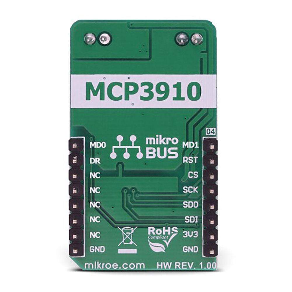
PINOUT DIAGRAM
This table shows how the pinout of the PWR Meter 2 Click Board™ corresponds to the pinout on the mikroBUS™ socket (the latter shown in the two middle columns).
| Notes | Pin | Pin | Notes | ||||
|---|---|---|---|---|---|---|---|
| Modulator OUT 1 | MD1 | 1 | AN | PWM | 16 | MD0 | Modulator OUT 0 |
| Chip Reset | RST | 2 | RST | INT | 15 | DR | Data Ready |
| SPI Chip Select | CS | 3 | CS | RX | 14 | NC | |
| SPI Clock | SCK | 4 | SCK | TX | 13 | NC | |
| SPI Data OUT | SDO | 5 | MISO | SCL | 12 | NC | |
| SPI Data IN | SDI | 6 | MOSI | SDA | 11 | NC | |
| Power supply | 3.3V | 7 | 3.3V | 5V | 10 | NC | |
| Ground | GND | 8 | GND | GND | 9 | GND | Ground |
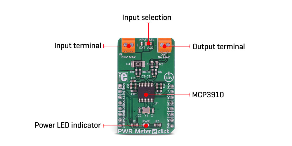
ONBOARD SETTINGS AND INDICATORS
| Label | Name | Default | Description |
|---|---|---|---|
| LD1 | PWR | Power LED indicator | |
| JP1 | INPUT SEL | Right | Monitoring input selection: left position external input, right position mikroBUS™ 3.3V power rail |
| TB1 | IN | Input terminal for external power monitoring | |
| TB2 | OUT | Output terminal for external power monitoring |
| General Information | |
|---|---|
Part Number (SKU) |
MIKROE-3150
|
Manufacturer |
|
| Physical and Mechanical | |
Weight |
0.03 kg
|
| Other | |
EAN |
8606018713530
|
Frequently Asked Questions
Have a Question?
Be the first to ask a question about this.