


Mikroelektronika d.o.o.
Balancer 2 Click Board™
Balancer 2 Click Board™
SKU: MIKROE-4058
Couldn't load pickup availability


Overview
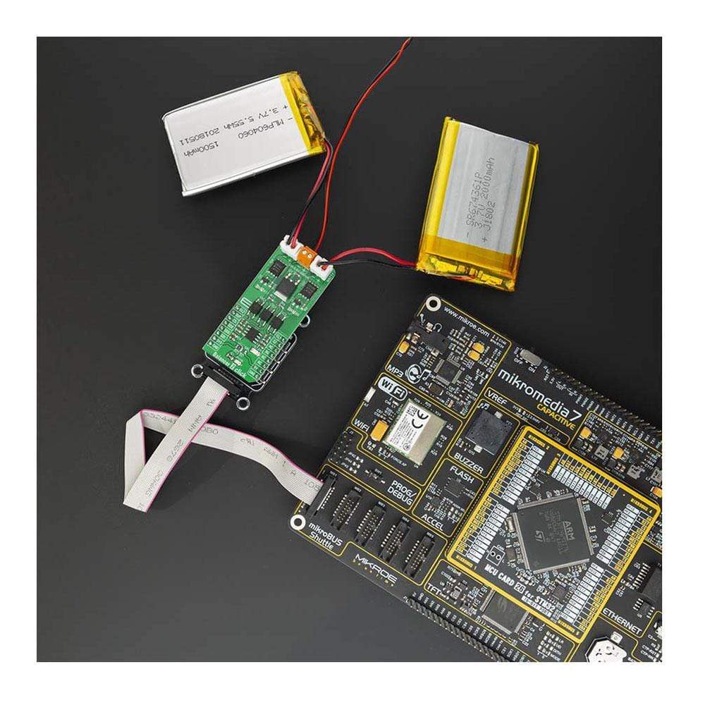
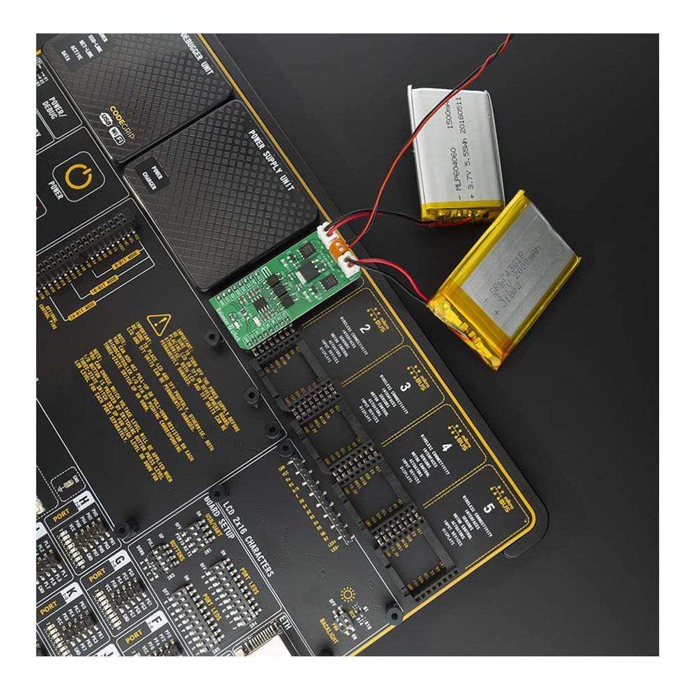
The Balancer 2 Click Board™ is an overvoltage protection device for a 2-series cell lithium-ion battery. Click contains two separate overvoltage battery detection circuits and automatic cell imbalance correction. It can be used for various applications, power tools, portable equipment, and instrumentation, to energy storage systems (ESS), while providing the output voltage at the same time. By utilizing an externally connected power supply, it can charge 2-cell Li-Ion batteries.
The Balancer 2 Click Board™ is supported by the mikroSDK compliant library, which includes functions that simplify software development. The Click Board™ comes as a fully tested product, ready to be used on a system equipped with mikroBUS™.
Downloads
How Does The Balancer 2 Click Board™ Work?
The Balancer 2 Click Board™ has two separate voltage battery monitoring circuits, overvoltage supply detection, and automatic cell balancing. The Balancer 2 Click Board™ monitors the voltages on each battery and correct voltage difference. Combined with a LiPo/Li-Ion battery charger, this Click board™ can be used in a wide range of applications that can benefit from reliable and efficient battery charging circuit.
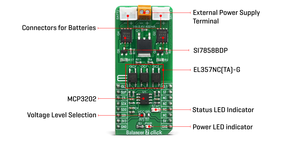
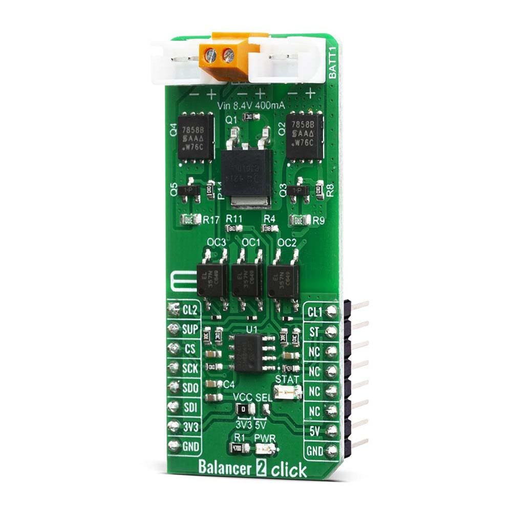
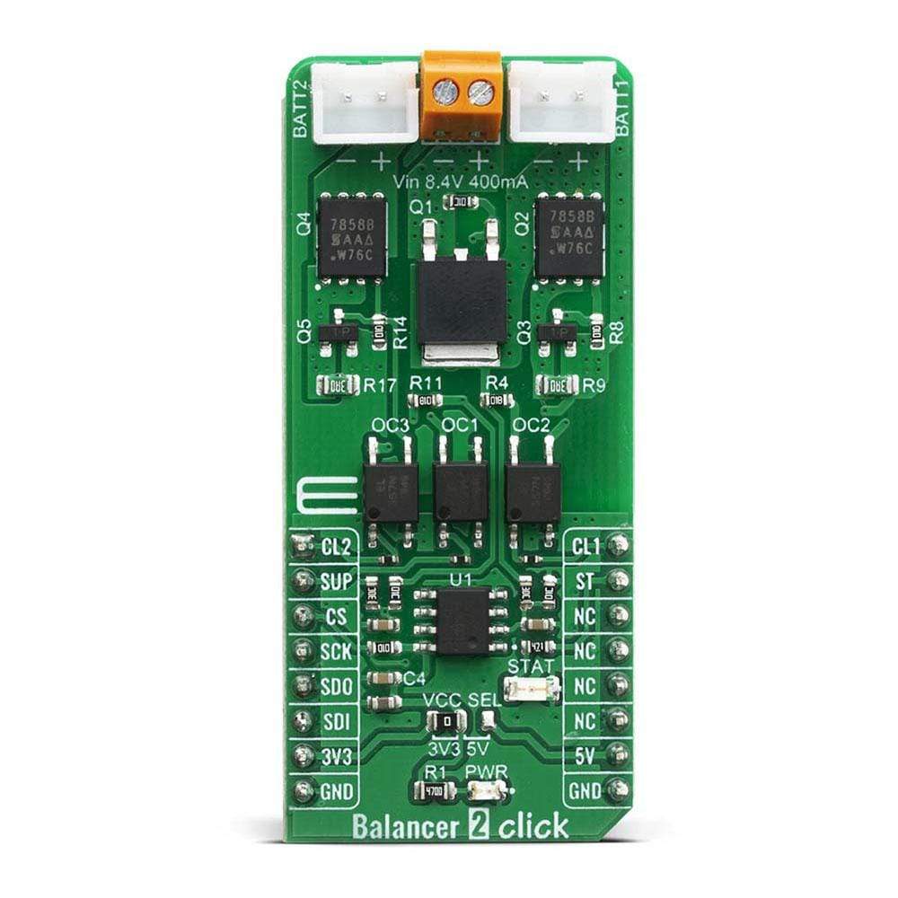
The Balancer 2 Click Board™ is designed to balance two LiPo/Li-Ion batteries, wired in serial. It contains all needed an analog circuitry, made of two separate blocks, for each battery, which is needed for the described device. Each block consists of one MOSFET, used as a power transistor - Si7858BDP, from Vishay Siliconix. Besides the MOSFET, the circuit also contains transistor needed for automatic gate bias regulation, based on the current running through the shunt resistors (R7 and R17). Each output is also optocoupled, in order to ensure very good reliability of the Click board™, regardless of the external power supply used. For that, EL357N-G photocouplers were used, from Everlight.
Two circuit blocks described above, combined, make the battery cell balancer. Besides that, this Click board™ has protection for the supply voltage. if the supply voltage is higher then 8.4V, the main P-Mosfet is power off and safe battery.
The third part of the Balancer 2 Click Board™ is voltage monitoring circuitry, which is based on the MCP3202, Dual Channel 12-Bit A/D Converter with SPI Serial Interface, from Microchip. The cell voltages are brought to the ADC input, through the dedicated voltage dividers, serving to conditionate the voltage signal levels to ADC inputs. That way direct output voltage is achieved, so the user can switch the cell independently based on the voltage parameters read.
The voltage level of the logic section can be selected via VCC SEL jumper, between 3.3V and 5V. This allows for both 3.3V and 5V capable MCUs to use the SPI communication lines properly.
SPECIFICATIONS
| Type | Battery charger |
| Applications | The Balancer 2 Click Board™ can be used for voltage monitor, power tools, battery balancing, portable equipment and instrumentation, to energy storage systems (ESS) |
| On-board modules | MCP3202, Dual Channel 12-Bit A/D Converter with SPI Serial Interface, from Microchip. |
| Key Features | Over-voltage protection, optocoupled outputs, independent cell voltage readings |
| Interface | GPIO,SPI |
| Compatibility | mikroBUS |
| Click board size | L (57.15 x 25.4 mm) |
| Input Voltage | 3.3V or 5V |
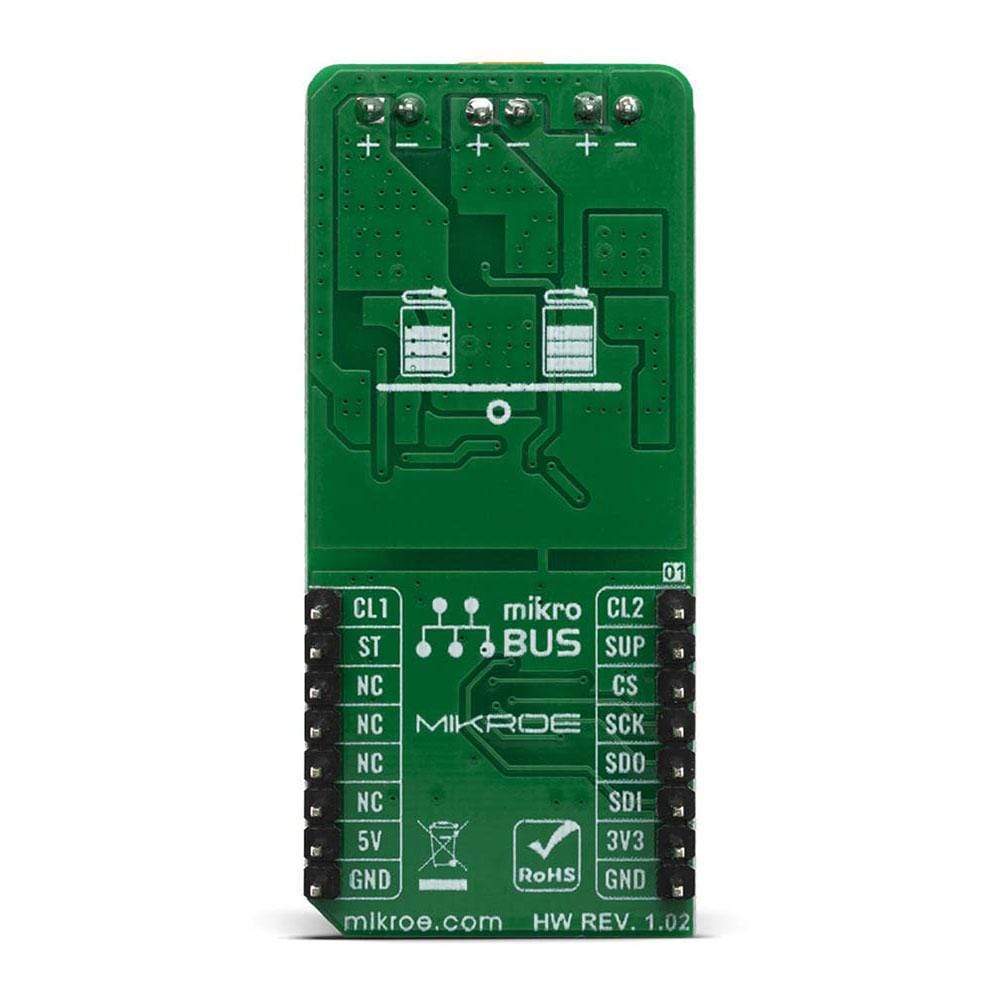
PINOUT DIAGRAM
This table shows how the pinout on thye Balancer 2 Click Board™ corresponds to the pinout on the mikroBUS™ socket (the latter shown in the two middle columns).
| Notes | Pin | Pin | Notes | ||||
|---|---|---|---|---|---|---|---|
| Cell 1 | CL1 | 1 | AN | PWM | 16 | CL2 | Cell 2 |
| Supply | SUP | 2 | RST | INT | 15 | ST | Status |
| SPI Chip Select | CS | 3 | CS | RX | 14 | NC | |
| SPI Clock | SCK | 4 | SCK | TX | 13 | NC | |
| SPI Data OUT | SDO | 5 | MISO | SCL | 12 | NC | |
| SPI Data IN | SDI | 6 | MOSI | SDA | 11 | NC | |
| Power Supply | 3.3V | 7 | 3.3V | 5V | 10 | 5V | Power Supply |
| Ground | GND | 8 | GND | GND | 9 | GND | Ground |
ONBOARD SETTINGS AND INDICATORS
| Label | Name | Default | Description |
|---|---|---|---|
| LD1 | STAT | - | Status LED indicator |
| VCC SEL | - | Left | Logic voltage level selection: left position 3.3V, right position 5V |
| LD2 | PWR | - | Power LED indicator |
BALANCER 2 CLICK ELECTRICAL SPECIFICATIONS
| Description | Min | Typ | Max | Unit |
|---|---|---|---|---|
| Battery balancing current | - | 250 | - | mA |
| Overvoltage Protection accuracy | - | 20 | - | mV |
| Input Voltage supply | - | 8.4 | - | V |
| Input Current supply | - | 400 | - | mA |
| General Information | |
|---|---|
Part Number (SKU) |
MIKROE-4058
|
Manufacturer |
|
| Physical and Mechanical | |
Weight |
0.022 kg
|
| Other | |
EAN |
8606018717156
|
Frequently Asked Questions
Have a Question?
Be the first to ask a question about this.