Overview
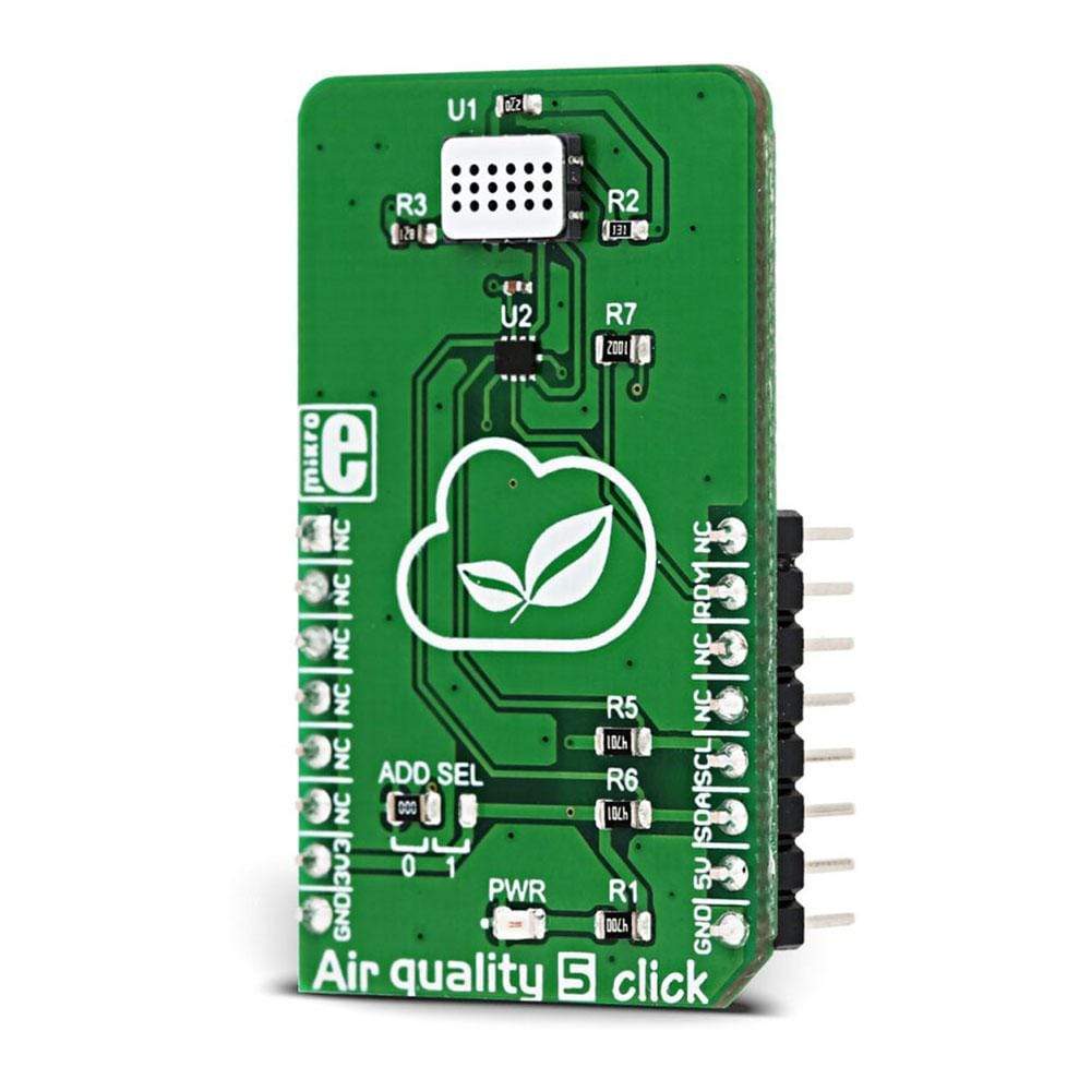
The Air Quality 5 Click Board™ is a triple MOS sensor on a single Click Board™, which can detect gas pollution for a number of different gases. The onboard sensor is specially designed to detect the pollution from automobile exhausts, as well as the gas pollution from the industrial or agricultural industry.
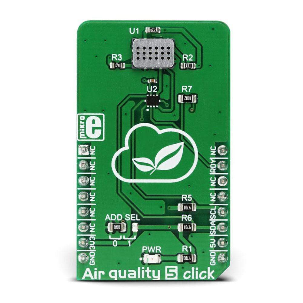
The Air Quality 5 Click Board™ uses the MiCS-6814, a compact MOS sensor with three fully independent sensing elements in one package: RED sensor, OX sensor, and NH3 sensor. Each of these sensors reacts with the specific type of gases, providing gas readings that including carbon monoxide (CO), nitrogen dioxide (NO2), ethanol (C2H5OH), hydrogen (H2), ammonia (NH3), methane (CH4), propane (C3H8), and isobutane (C4H10). Measurement conversion is handled by the onboard 12-bit ADC converter and it is available via the I2C interface.
Downloads
The Air Quality 5 Click Board™ is a triple MOS sensor which can detect gas pollution for a number of different gases. The onboard sensor is specially designed to detect the pollution from automobile exhausts, as well as the gas pollution from the industrial or agricultural industry. The Air Quality 5 Click Board™ uses the MiCS-6814, a compact MOS sensor with three fully independent sensing elements in one package: RED sensor, OX sensor, and NH3 sensor. Each of these sensors reacts with the specific type of gases, providing gas readings that including carbon monoxide (CO), nitrogen dioxide (NO2), ethanol (C2H5OH), hydrogen (H2), ammonia (NH3), methane (CH4), propane (C3H8), and isobutane (C4H10). Measurement conversion is handled by the onboard 12bit ADC converter and it is available via the I2C interface.
Featuring the MiCS-6814 MOS sensor with increased robustness for harsh environments, low noise 12bit onboard ADC converter, short preheat time requirement and reasonably high sensitivity, this Click board™ can be used for development of various environmental pollution measurement and detection applications, or various types of gas alarms in automotive industry or production/manufacturing chambers with a high risk of gas poisoning.
How Does The Air Quality 5 Click Board™ Work?
The Air Quality 5 Click Board™ contains the MiCS-6814, a compact triple MOS sensor from SGX Sensortech, with three fully independent sensors. The Click board™ also contains the ADS1015, a low-power 12bit ADC with Internal reference, and programmable comparator, from Texas Instruments. The MiCS-6814 sensor consists of three independent metal oxide sensors, heated by three separate heater structures. Chemicals which are absorbed by the metal oxide surface, change the resistive properties of the sensor. The typical baseline resistance may vary a lot from a sensor to a sensor and it can be affected by the measurement conditions, sensor aging, and several other factors. Therefore, it is recommended to periodically monitor the relative change of the sensing resistance against the baseline resistance. It allows development of applications which detect relative gas concentration changes, rather than measuring the absolute gas concentration values.
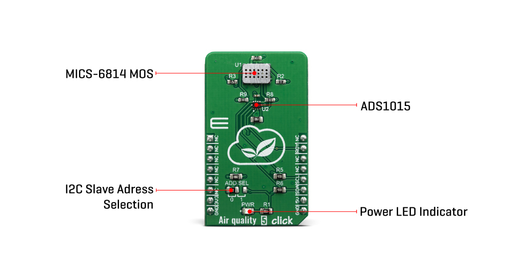
As mentioned, there are three sensors on the same die. Each of them reacts with a different type of gas. There is a RED sensor which reacts with the reducing gas agents, an OX sensor which reacts with the oxidizing gas agents, and lastly, a sensor which reacts with NH3. These sensors provide readings (in ppm) for eight different gasses, which are of interest to be monitored in the automotive, industry or agriculture polluted atmosphere.
Every heating structure is powered from the mikroBUS™ 5V power rail via the resistor, recommended by the manufacturer. This ensures the maximum life cycle of the device to be achieved since current ratings above the recommended would damage the sensors and heaters. It is recommended to pre-heat the sensors for at least 30 seconds before valid readings can be made. The longer the pre-heat period is, the more accurate the measurement becomes.
The changes of the sensor resistance are measured and sampled by the onboard ADC. The ADS1015 ADC has four multiplexed inputs, of which three are connected to each of the sensors. The ADC has an internal reference, it is very simple to operate, it offers inputs that can handle voltages across the sensors, and require a low number of external components. These attributes make it perfectly suitable for the Air Quality 5 Click Board™. In addition, it is possible to change the slave I2C address of the device. This is done by using the SMD jumper, labeled as ADD SEL. This jumper allows selection of the I2C LSB bit state (0 or 1), allowing more than one Click board™ on the same I2C bus.
The ADS1015 IC also has a READY pin, which is used to signal or alert the host MCU that the conversion is ready for reading. This pin is routed to the mikroBUS™ INT pin and it is labeled as RDY. More information on how to configure and use this pin can be found in the ADS1015 datasheet.
Both 5V and 3.3V rails from the mikroBUS™ are used. The ADC is powered by 3.3V rail, but the sensor requires 5V rail to be used as well. Therefore, the Air Quality 5 Click Board™ requires both 3.3V and 5V pins to be supplied with the power.
SPECIFICATIONS
| Type | Air Quality ,Gas |
| Applications | Various environmental pollution measurement and detection applications, or various types of gas alarms in the automotive industry or production/manufacturing chambers with a high risk of gas poisoning. |
| On-board modules | MiCS-6814, a compact triple MOS sensor from SGX Sensortech; ADS1015, a low-power 12bit ADC with Internal reference and programmable comparator, from Texas Instruments. |
| Key Features | Increased robustness for harsh environments, low noise 12bit onboard ADC converter, reasonably high accuracy, three separate sensors on the same die for sensing of the number of different types of gases. |
| Interface | I2C |
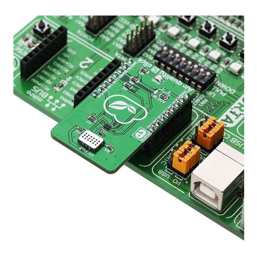
| Compatibility | mikroBUS |
| Click board size | M (42.9 x 25.4 mm) |
| Input Voltage | 3.3V,5V |
PINOUT DIAGRAM
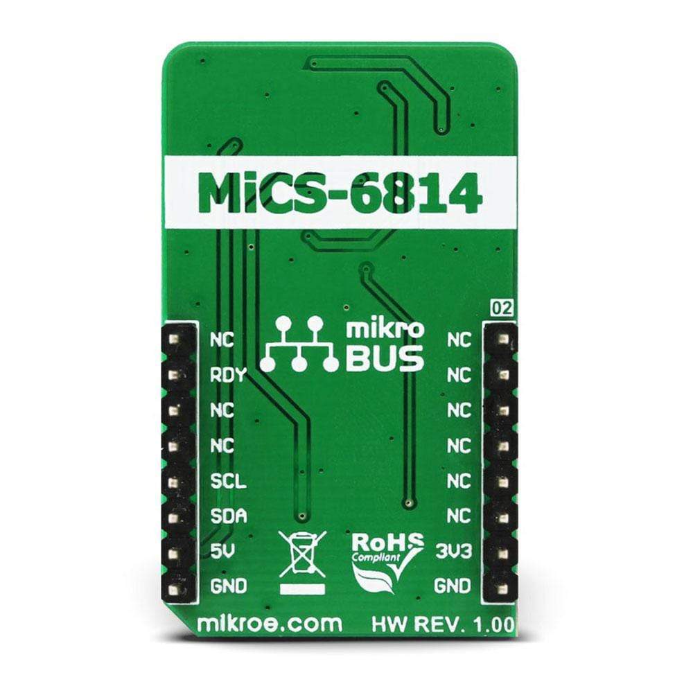
This table shows how the pinout of the Air Quality 5 Click Board™ corresponds to the pinout on the mikroBUS™ socket (the latter shown in the two middle columns).
| Notes | Pin |  |
Pin | Notes | |||
|---|---|---|---|---|---|---|---|
| NC | 1 | AN | PWM | 16 | NC | ||
| NC | 2 | RST | INT | 15 | RDY | Ready | |
| NC | 3 | CS | RX | 14 | NC | ||
| NC | 4 | SCK | TX | 13 | NC | ||
| NC | 5 | MISO | SCL | 12 | SCL | I2C Clock | |
| NC | 6 | MOSI | SDA | 11 | SDA | I2C Data | |
| Power supply | 3.3V | 7 | 3.3V | 5V | 10 | 5V | Power supply |
| Ground | GND | 8 | GND | GND | 9 | GND | Ground |
ONBOARD SETTINGS AND INDICATORS
| Label | Name | Default | Description |
|---|---|---|---|
| PWR | PWR | - | Power LED indicator |
| ADD SEL | ADD SEL | Left | I2C address bit selection: left position 0, right position 1 |
| General Information | |
|---|---|
Part Number (SKU) |
MIKROE-3056
|
Manufacturer |
|
| Physical and Mechanical | |
Weight |
0.019 kg
|
| Other | |
Country of Origin |
|
HS Code Customs Tariff code
|
|
EAN |
8606018713172
|
Warranty |
|
Frequently Asked Questions
Have a Question?
Be the first to ask a question about this.


