


Mikroelektronika d.o.o.
BIG 7-SEG R Click Board™
BIG 7-SEG R Click Board™
SKU: MIKROE-2269
Couldn't load pickup availability


Overview
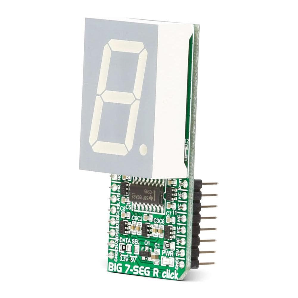
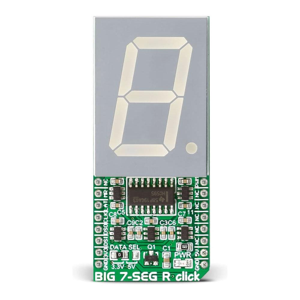
The BIG 7-Seg R Click Board™ is what you need if you want to add a seven-segment LED display to your project. This click features an SC10-21SRWA seven-segment display. Communication between the MCU and the SC10-21SRWA display is established via serial-IN, parallel-OUT shift register 74HC595 IC.
The BIG 7-Seg R Click Board™ runs on either 3.3V or 5V power supply and communicates with the target MCU over an SPI interface.
Downloads
The BIG 7-Seg R Click Board™ is what you need if you want to add a seven-segment LED display to your project. This Click Board™ features an SC10-21SRWA seven-segment display. Communication between the MCU and the SC10-21SRWA display is established via serial-IN, parallel-OUT shift register 74HC595 IC.
The BIG 7-Seg R Click Board™ runs on either 3.3V of 5V power supply and communicates with the target MCU over an SPI interface.
Display
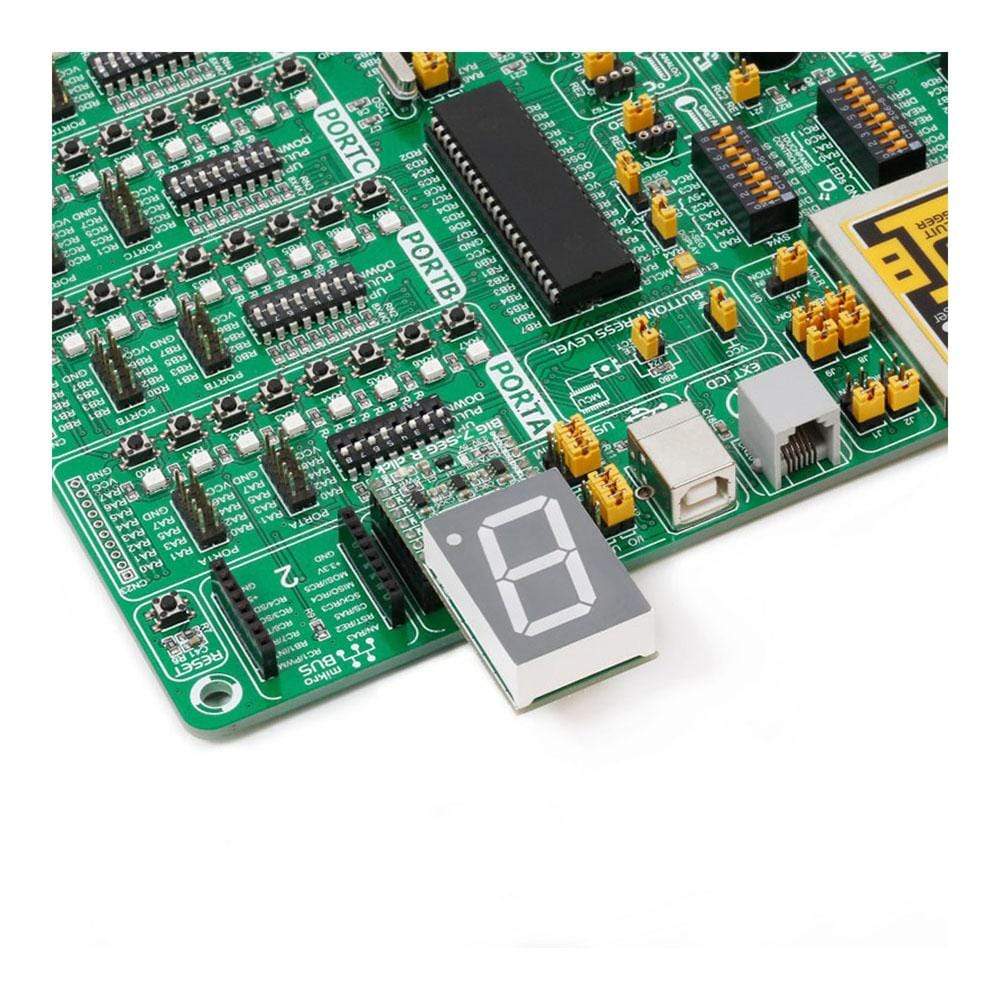
The BIG 7-Seg R Click Board™ displays letters, numbers and symbols in highly readable form. It can be used in any simple interface and combined with other Click Board™s. The color of the displayed character is red, as the R in the name of the Click Board™ states.
Light Intensity
The light intensity on the display is controlled via the PWM pin on the board.
Applications
Adding a seven-segment LED display to your device with SPI interface.
SPECIFICATIONS
| Type | 7-segment,LED Segment |
| Applications | Adding a seven-segment LED display to your device with SPI interface |
| On-board modules | SC10-21SRWA seven-segment display, parallel-OUT shift register 74HC595 IC |
| Key Features | 1.0 inch digit height, Standard: grey face, white segment, Low current operation |
| Interface | GPIO,PWM,SPI |
| Compatibility | mikroBUS |
| Click board size | L (57.15 x 25.4 mm) |
| Input Voltage | 3.3V or 5V |
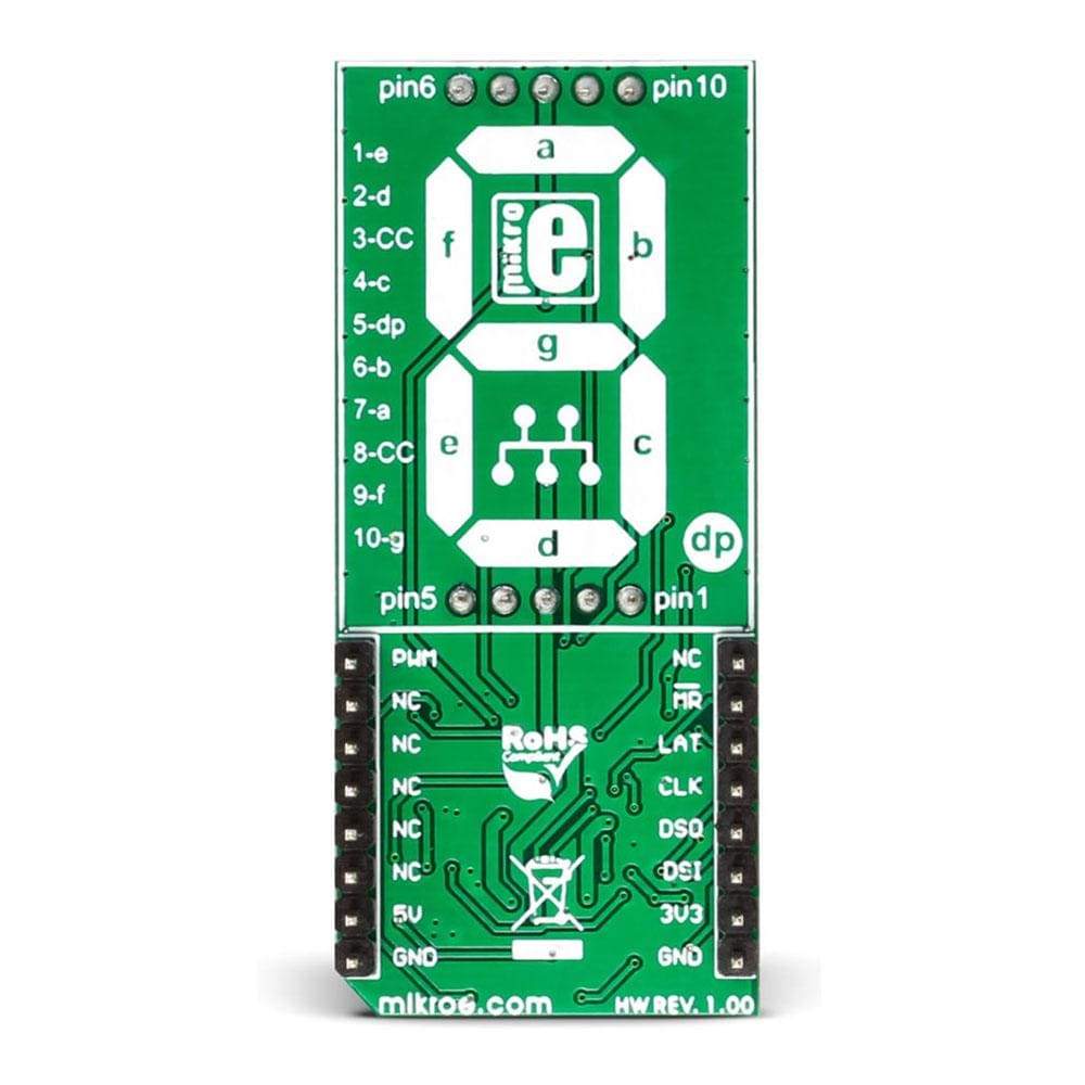
PINOUT DIAGRAM
This table shows how the pinout on the BIG 7-Seg R Click Board™ corresponds to the pinout on the mikroBUS™ socket (the latter shown in the two middle columns).
| Notes | Pin | Pin | Notes | ||||
|---|---|---|---|---|---|---|---|
| NC | 1 | AN | PWM | 16 | PWM | Display light intensity control | |
| Master Reset for 74HC595 | MR | 2 | RST | INT | 15 | NC | |
| Latch for 74HC595 | LAT | 3 | CS | TX | 14 | NC | |
| Clock for 74HC595 | CLK | 4 | SCK | RX | 13 | NC | |
| Serial Data from 74HC595 to MCU | DSO | 5 | MISO | SCL | 12 | NC | |
| Serial Data from MCU to 74HC595 | DSI | 6 | MOSI | SDA | 11 | NC | |
| Data line when interfaced with 3.3V MCU | 3.3V | 7 | +3.3V | +5V | 10 | 5V | Data line when interfaced with 5V MCU and also power supply pin for display and the whole click hardware |
| Ground | GND | 8 | GND | GND | 9 | GND | Ground |
JUMPERS AND SETTINGS
Information about onboard jumpers:
| Designator | Name | Default Position | Default Option | Description: describe the use + list all options with respective descriptions |
|---|---|---|---|---|
| JP1 | Logic level | Left | 3.3V | Logic Level Selection toward host mcu 3.3V/5V, left position 3.3V, right position 5V |
| General Information | |
|---|---|
Part Number (SKU) |
MIKROE-2269
|
Manufacturer |
|
| Physical and Mechanical | |
Weight |
0.03 kg
|
| Other | |
EAN |
8606018717972
|
Frequently Asked Questions
Have a Question?
Be the first to ask a question about this.