Overview
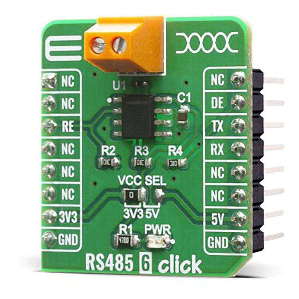
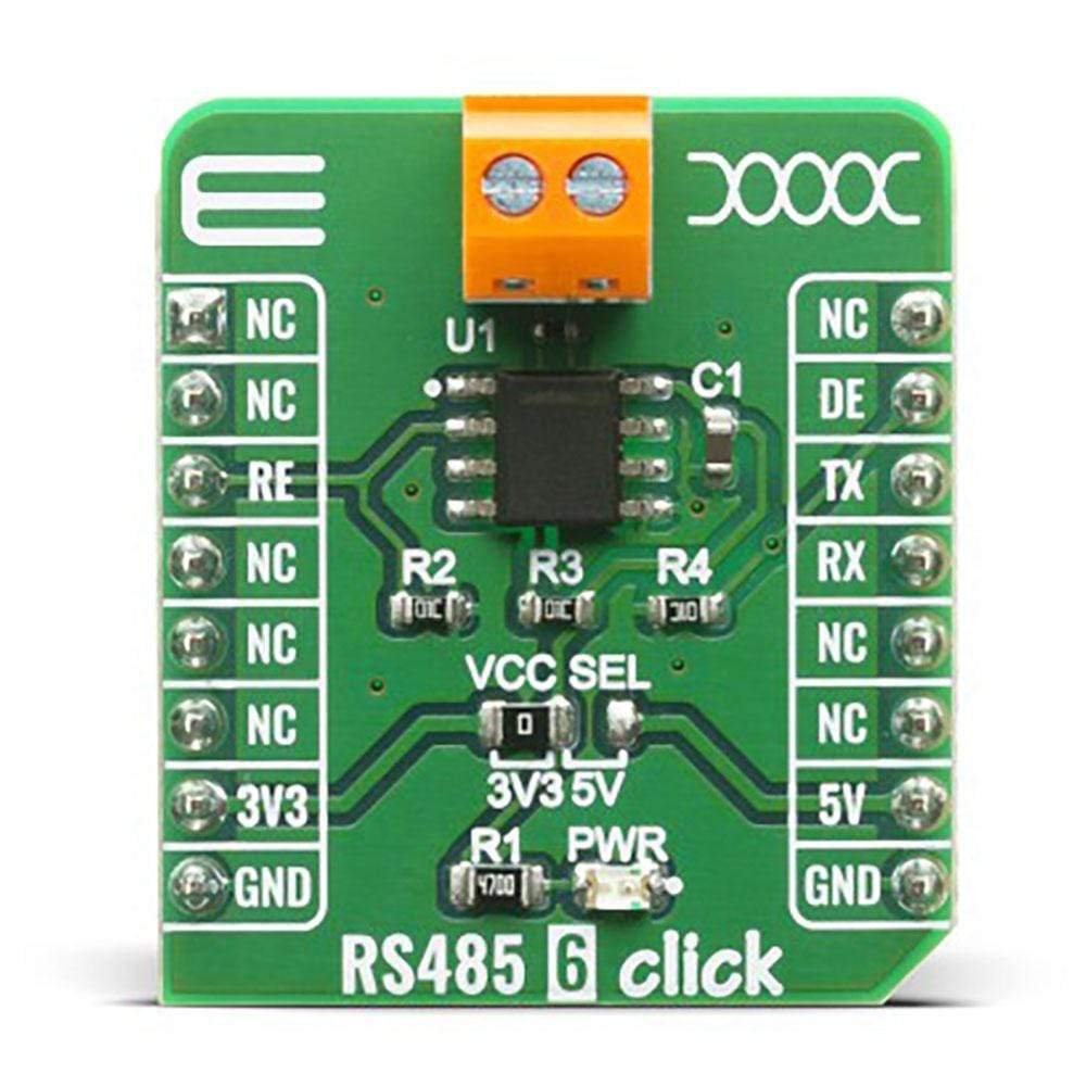
The RS485 6 Click Board™ offers a half-duplex RS-485 communication with integrated surge protection, which can be used as an interface between the TTL level UART and the RS485 communication bus. It is based on THVD1429DT, a transceiver from Texas Instruments with a signalling rate of up to 20 Mbps. This device features a wide common-mode voltage range from 3.3V to 5V, which makes it suitable for multi-point applications over long cable runs and noisy areas thanks to the integrated transient voltage suppressor (TVS) diodes. This device and type of network is perfectly suitable for wireless infrastructure, building automation, HVAC systems or factory automation, and many more.
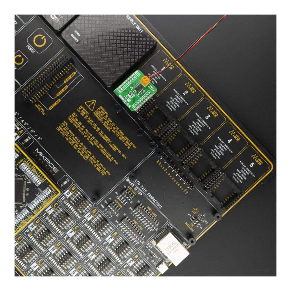
The RS485 6 Click is supported by a mikroSDK compliant library, which includes functions that simplify software development. This Click Board™ comes as a fully tested product, ready to be used on a system equipped with the mikroBUS™ socket.
Downloads
How Does The RS485 6 Click Board™ Work?
The RS485 6 Click Board™ is designed to offer you easy usage and testing of the THVD1429DT half-duplex RS485 transceiver. One of the most important features is surge protection which is achieved by integrating transient voltage suppressor (TVS) diodes in the package. This feature provides a substantial increase in reliability for better immunity to noise transients coupled to the data cable, eliminating the need for external protection components.
An RS-485 bus consists of multiple transceivers connecting in parallel to a bus cable. To eliminate line reflections, each cable end is terminated with a termination resistor whose value matches the characteristic impedance of the cable. This method, known as parallel termination, allows for higher data rates over longer cable length. This device supports up to 256 Bus Nodes in one network with higher data rates up to 20 Mbps, in cases where the interconnect is short enough (or has suitably low attenuation at signal frequencies) to not degrade the data.
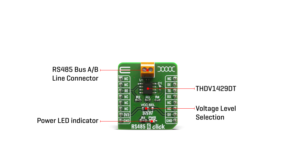
The THVD1329DT supports several functional modes that can be selected by using RE and DE pins on the mikroBUS connector. To know more how to use these modes take a look at the "Device Functional Modes" table below. For communication with the RS485 6 Click standard UART communication can be used.
This device offer several protections for the pins connected to a bus line, such as: Electrostatic Discharge (ESD) Protection against ±16-kV HBM and ±8-kV contact discharge, Electrical Fast Transient (EFT) Protection where inductive loads such as relays, switch contactors, or heavy-duty motors can create high-frequency bursts during transition and Surge transients that often result from lightning strikes (direct strike or an indirect strike which induce voltages and currents), or the switching of power systems, including load changes and short circuit switching. These transients are often encountered in industrial environments, such as factory automation and power-grid systems.
Since this device feature a wide common-mode voltage range which makes them suitable for multi-point applications over long cable runs. The RS485 6 Click Board™ can be supplied and interfaced with both 3.3V and 5V without the need for any external components. The onboard SMD jumper labeled as VCC SEL allows voltage selection for interfacing with both 3.3V and 5V microcontrollers.
SPECIFICATIONS
| Type | RS485 |
| Applications | This device is perfectly suitable for wireless infrastructure, building automation, HVAC systems or factory automation, smart meters. |
| On-board modules | THVD1329DT a half-duplex RS-485 communication with integrated surge protection from Texas Instruments |
| Key Features | Surge protection on the RS485 Line, up to 256 nodes, signaling rate of up to 20 Mbps. |
| Interface | UART |
| Compatibility | mikroBUS |
| Click board size | S (28.6 x 25.4 mm) |
| Input Voltage | 3.3V or 5V |
PINOUT DIAGRAM
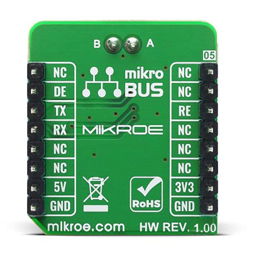
This table shows how the pinout on the RS485 6 Click Board™ corresponds to the pinout on the mikroBUS™ socket (the latter shown in the two middle columns).
| Notes | Pin |  |
Pin | Notes | |||
|---|---|---|---|---|---|---|---|
| NC | 1 | AN | PWM | 16 | NC | ||
| NC | 2 | RST | INT | 15 | DE | Driver enable(active hight) | |
| Receiver Enable | RE | 3 | CS | RX | 14 | TXD | UART transmit |
| NC | 4 | SCK | TX | 13 | RXD | UART Receive | |
| NC | 5 | MISO | SCL | 12 | NC | ||
| NC | 6 | MOSI | SDA | 11 | NC | ||
| Power Supply | 3.3V | 7 | 3.3V | 5V | 10 | 5V | Power Supply |
| Ground | GND | 8 | GND | GND | 9 | GND | Ground |
RS485 6 CLICK ELECTRICAL SPECIFICATIONS
| Description | Min | Typ | Max | Unit |
|---|---|---|---|---|
| Supply Voltage Range | -0.5 | - | 7 | V |
| Signaling Rate | - | - | 20 | Mbps |
| Bus Voltage | -15 | - | 15 | V |
| Receiver Output Current | -24 | - | 24 | mA |
| Electrostatic Discharge | - | +/-16 | - | kV |
DEVICE FUNCIONAL MODES
| INPUT | ENABLE | OUTPUTS | FUNCTION | |
|---|---|---|---|---|
| D | DE | A | B | |
| H | H | H | L | Active drive bus hight |
| L | H | L | H | Active drive bus low |
| X | L | Z | Z | Drive disabled |
| X | OPEN | Z | Z | Driver disabled by default |
| OPEN | H | H | L | Actively drive bus high by default |
ONBOARD SETTINGS AND INDICATORS
| Label | Name | Default | Description |
|---|---|---|---|
| LD1 | PWR | - | Power LED indicator |
| JP2 | VCC SEL | Left | Power supply voltage selection: left position 3V3, right position 5V |
| General Information | |
|---|---|
Part Number (SKU) |
MIKROE-3993
|
Manufacturer |
|
| Physical and Mechanical | |
Weight |
0.016 kg
|
| Other | |
Country of Origin |
|
HS Code Customs Tariff code
|
|
EAN |
8606018718429
|
Warranty |
|
Frequently Asked Questions
Have a Question?
Be the first to ask a question about this.

