Overview
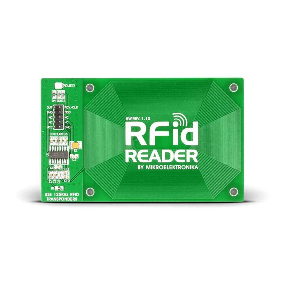
The RFid Reader Board has been designed for reading identification cards (RFid Cards) using radio waves. This accessory board comes equipped with a 125 KHz RF transmitter and receiver, and an EM4095 controller chip. While the included receiver/transmitter module with antenna and a 2x5 male connector allows the reader board to get connected with a microcontroller on the development system, EM409S is used for AM modulation/demodulation or as a driver for the antenna.
The RFid Reader Board works on the basis of amplitude modulation of radio waves and electromagnetic induction. Its primary functions are energizing, demodulation, and decoding. The board can be connected to microcontrollers or PC for encoding the data read from RFid tags. This signal is coded using standard Manchester coding. The additional board makes use of the provided antenna to receive data stored on the identification card (RFid Card). The reader is powered via a development system it is connected to. It comes fitted with a power supply LED indicator.
Downloads
EM4095 CMOS integrated transceiver
The EM4095 (also known as P4095) chip is a 125 KHz-134 KHz, Read/Write analog front end for RFID basestation. This circuit, which is meant for use in an RFID basestation, carries out antenna driving with carrier frequency while communicating with a microprocessor via simple interface. It does AM modulation of the field for writable transponder and AM demodulation of the antenna signal modulation induced by the transponder.
Operating Voltage
The RFid Reader Board operates on 5V power supply only. For connecting it to 3.3V systems, the user must use voltage translators on communication lines.
Applications
The RFid Reader Board can be used to read code from 125 kHz RFid tags or identification cards. This makes it ideal for use in car immobilizers, hand held reader and designing low cost readers.
| General Information | |
|---|---|
Part Number (SKU) |
MIKROE-262
|
Manufacturer |
|
| Physical and Mechanical | |
Weight |
0.032 kg
|
| Other | |
Warranty |
|
Country of Origin |
|
HS Code Customs Tariff code
|
|
EAN |
8606015072029
|
Frequently Asked Questions
Have a Question?
Be the first to ask a question about this.

