


Mikroelektronika d.o.o.
Brushless 14 Click Board™
Brushless 14 Click Board™
SKU: MIKROE-4648
Couldn't load pickup availability


Overview
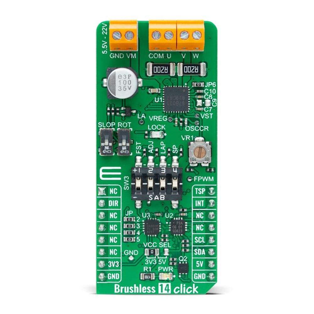
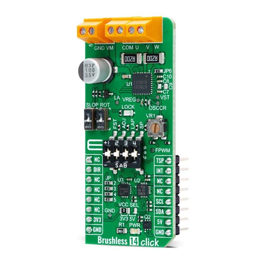
The Brushless 14 Click Board™ is a compact add-on board suitable for controlling BLDC motors with any MCU. This board features the TB67B001FTG, a three-phase, brushless, Hall sensorless driver IC from Toshiba Semiconductor. It comes with a 150-degree wide-angle commutation drive, contributing to lower vibration and motor noise, while a rotation speed up to 30,000rpm (rotations per minute when a 4-pole motor is used) can be achieved through a high-speed PWM and improved cooling.
This Brushless 14 Click Board™ makes the perfect solution for delivering quiet, cool operation to home appliances and office automation equipment.
Downloads
How Does The Brushless 14 Click Board™ Work?
The Brushless 14 Click Board™ as its foundation uses the TB67B001FTG, a three-phase PWM chopper driver for sensorless brushless motors from Toshiba Semiconductor. It controls motor rotation speed by changing the PWM duty cycle based on the speed control input. This Click board™ offers an energy-saving solution and quiet motor operation in brushless DC (BLDC) motors used for various applications.

The TSP signal, routed to the PWM signal of the mikroBUS™ socket, starts up and stops the motor operation and controls the output PWM duty to control the rotation speed of the motor. The procedure moves as follows: DC resolution mode - Forced commutation mode - Sensorless mode. Start-Up may fail when the initial rotor position is irregular because they do not synchronize in the forced commutation mode. In this case, adjustment to synchronize the forced commutation frequency to the motor rotation is necessary by adjusting the FST signal of the TB67B001FTG and the input voltage of the VST pin through the VR1 potentiometer to move the operation to the Sensorless mode.
In forced commutation mode in Start-Up, the motor operates under the following condition: lead angle = 0°, 120° commutation, and without soft switching. The operation changes automatically to the configured mode by setting the LA pin, LAP, and SLOP switches when the process switches to the Sensorless mode. Six types of drives (120°, 135°, and 150° commutation with and without soft switching) can be selected by SLOP and LAP switches.
The TSP pin can select pulse duty control or analog voltage control by the SP pin of the SW3 switch. Besides, the TSP signal can also adjust the output PWM duty by the configuration of ADJ0-3 channels done by DAC43608, a low-power, eight-channel, digital-to-analog converter. The desired value on the lead angle LA pin the TC78B042FTG and FPWM (output PWM frequency selection) is also obtained by the DAC3608, which establishes communication with MCU via I2C serial communication. The rotation speed of lead angle switching is selectable through the onboard ROT switch. When the most appropriate lead angle is set, the efficiency is improved, and the noise is reduced.
In addition to I2C communication, several GPIO pins connected to the mikroBUS™ socket pins are also used. The rotation direction of the motor can be switched by a DIR pin, routed to the RST signal of the mikroBUS™ socket. While switching the rotation direction, first stop the motor, turn off the output by the TSP pin, and then switch the rotation direction by changing the configuration of the DIR pin. Besides, it is possible to detect the occurrence of motor lock events where the indication of such a condition is performed using the LED indicator labeled as LOCK and rotation speed where the information is forwarded to the MCU via the PCA9538 expander port.
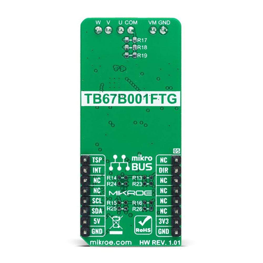
The user is left with the option of adding pull-up (R13-R16) or pull-down (R23-R26) resistors as desired for their applications and activating and deactivating the selected ADJ channels using jumper JP2-JP5. Also, when the motor is vibrating by the external factor, it may happen not to start operating normally. In such a case, the motor can start operating normally by adding the external resistances of R17-R19 to provide the offset voltage in the position detection comparator inside the TB67B001FTG.
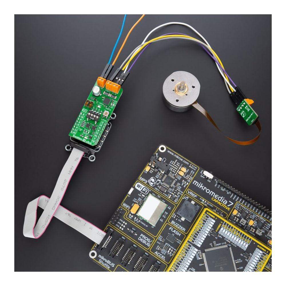
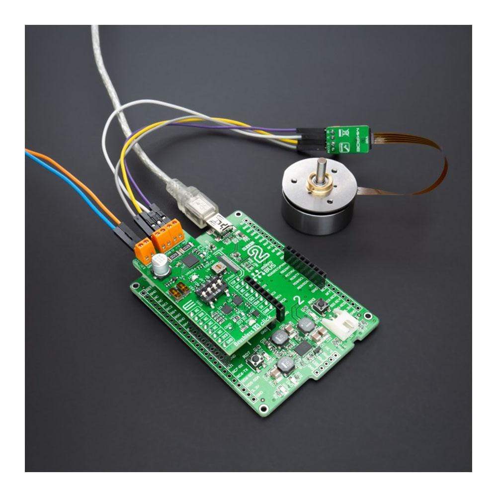
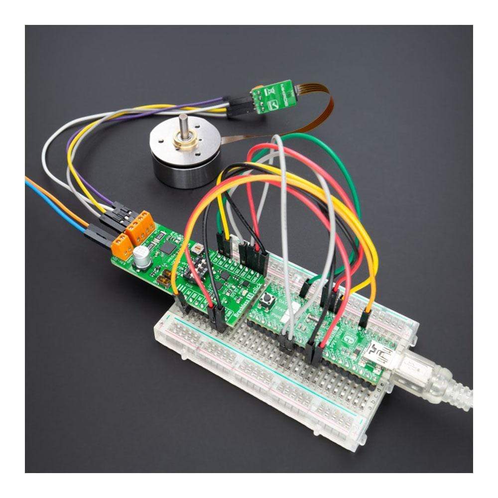
The Brushless 14 Click Board™ supports an external power supply for the motor, which can be connected to the input terminal labeled as VM and should be within the range of 5.5V to 22V, and the next one marked with U, V, W, and COM are terminals on which the BLDC motor needs to be connected. The absolute maximum rating of the power supply voltage is 25V (3A maximum current), which must not be exceeded, even for a moment. Do not exceed any of these ratings!
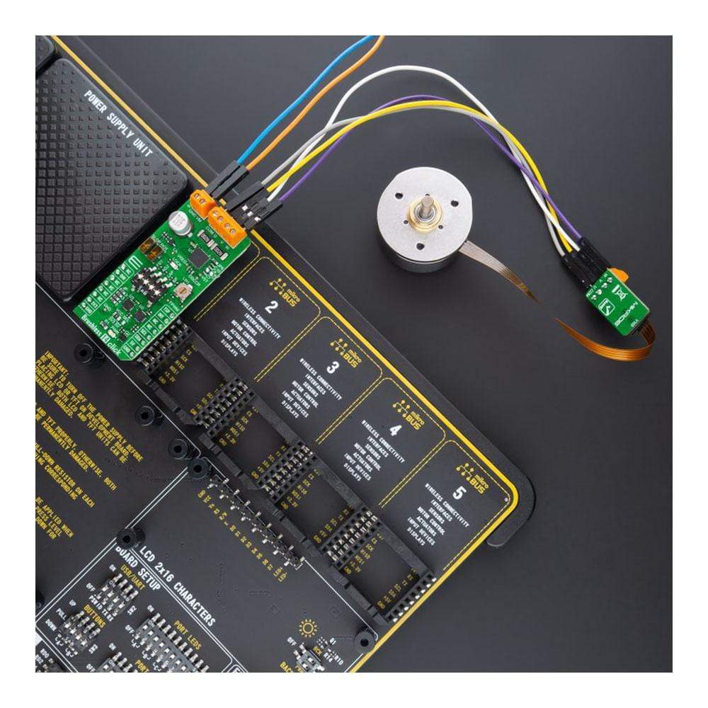
NOTE: The Brushless 14 Click Board™ can be connected to all sensorless BLDC motors with a flexprint port using the additional ZIF to Terminal Block for BLDC adapter that Mikroe has in its offer.
The Brushless 14 Click Board™ can operate with both 3.3V and 5V logic voltage levels selected via the VCC SEL jumper. This way, it is allowed for both 3.3V and 5V capable MCUs to use communication lines properly. However, the Click board™ comes equipped with a library containing easy-to-use functions and an example code that can be used, as a reference, for further development.
Specifications
| Type | Brushless |
| Applications | The Brushless 14 Click Board™ offers an energy-saving solution and quiet motor operation in brushless DC (BLDC) motors used for various applications |
| On-board modules | TB67B001FTG - three-phase PWM chopper driver for sensorless brushless motors from Toshiba Semiconductor |
| Key Features | Sensorless drive in three-phase full-wave mode, PWM chopper control, adjustable output PWM, lead angle control, overlapping commutation, rotation-speed and lock detection, and more |
| Interface | I2C,GPIO |
| Compatibility | mikroBUS |
| Click board size | L (57.15 x 25.4 mm) |
| Input Voltage | 3.3V or 5V,External |
Pinout Diagram
This table shows how the pinout on the Brushless 14 Click Board™ corresponds to the pinout on the mikroBUS™ socket (the latter shown in the two middle columns).
| Notes | Pin | Pin | Notes | ||||
|---|---|---|---|---|---|---|---|
| NC | 1 | AN | PWM | 16 | TSP | Rotation Speed Command | |
| Forward/Reverse Direction | DIR | 2 | RST | INT | 15 | INT | Interrupt |
| NC | 3 | CS | RX | 14 | NC | ||
| NC | 4 | SCK | TX | 13 | NC | ||
| NC | 5 | MISO | SCL | 12 | SCL | I2C Clock | |
| NC | 6 | MOSI | SDA | 11 | SDA | I2C Data | |
| Power Supply | 3.3V | 7 | 3.3V | 5V | 10 | 5V | Power Supply |
| Ground | GND | 8 | GND | GND | 9 | GND | Ground |
Onboard settings and indicators
| Label | Name | Default | Description |
|---|---|---|---|
| LD1 | PWR | - | Power LED Indicator |
| LD2 | LOCK | - | Lock Detect LED Indicator |
| JP1 | VCC SEL | Left | Logic Level Voltage Selection 3V3/5V: Left position 3V3, Right position 5V |
| JP2-JP5 | JP | Populated | ADJ Channels Selection |
| SW1 | SLOP | - | Soft-Switching Selection |
| SW2 | ROT | - | Rotation Speed of Lead Angle Switching |
| SW3 | SW3 | - | Multipurpose Switch |
| VR1 | VR1 | - | VST Duty Cycle Setting Trimmer |
Brushless 14 Click electrical specifications
| Description | Min | Typ | Max | Unit |
|---|---|---|---|---|
| Supply Voltage VCC | 3.3 | - | 5 | V |
| Supply Voltage VM | 5.5 | - | 22 | V |
| Maximum Output Voltage | 0 | - | 25 | V |
| Maximum Output Current | - | - | 3 | A |
| Operating Temperature Range | -40 | +25 | +105 | °C |
| General Information | |
|---|---|
Part Number (SKU) |
MIKROE-4648
|
Manufacturer |
|
| Physical and Mechanical | |
Weight |
0.02 kg
|
| Other | |
EAN |
8606027383328
|
Frequently Asked Questions
Have a Question?
Be the first to ask a question about this.