
Mikroelektronika d.o.o.
Stepper Click Board™
Stepper Click Board™
SKU: MIKROE-1528
Couldn't load pickup availability


Overview
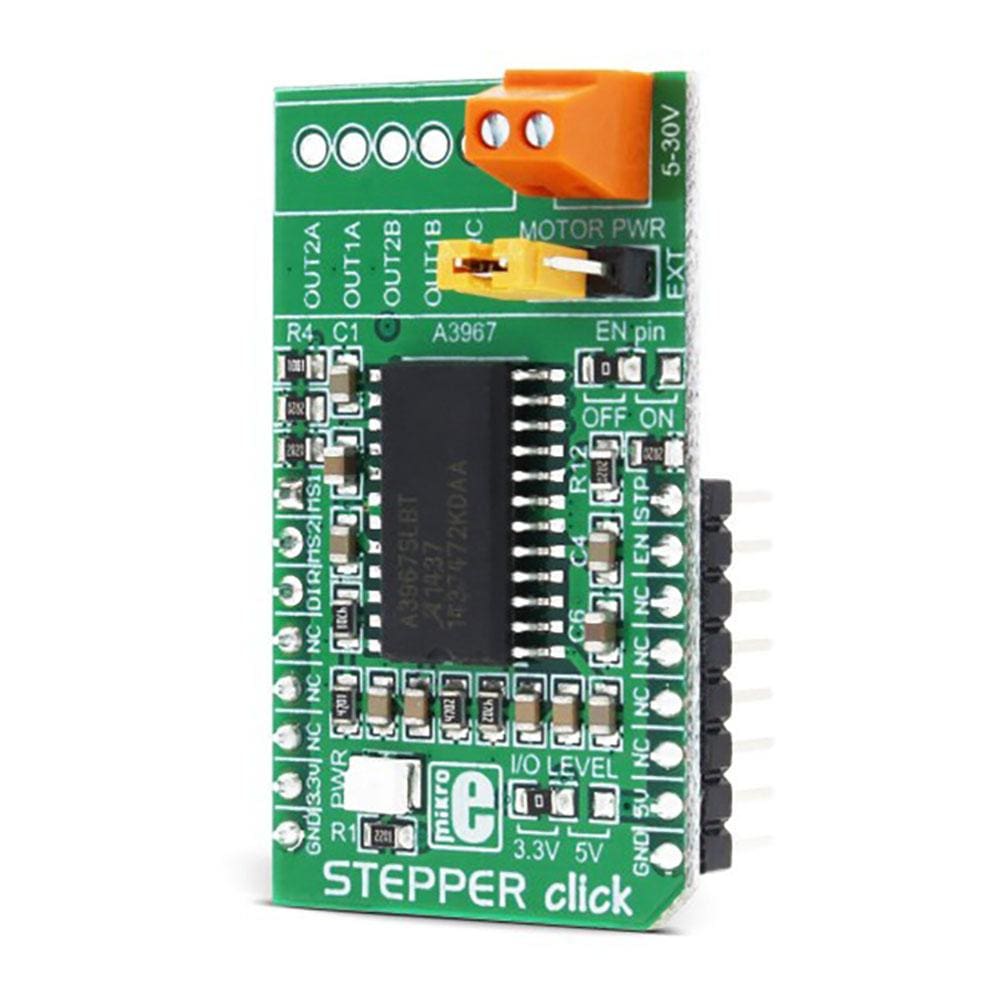
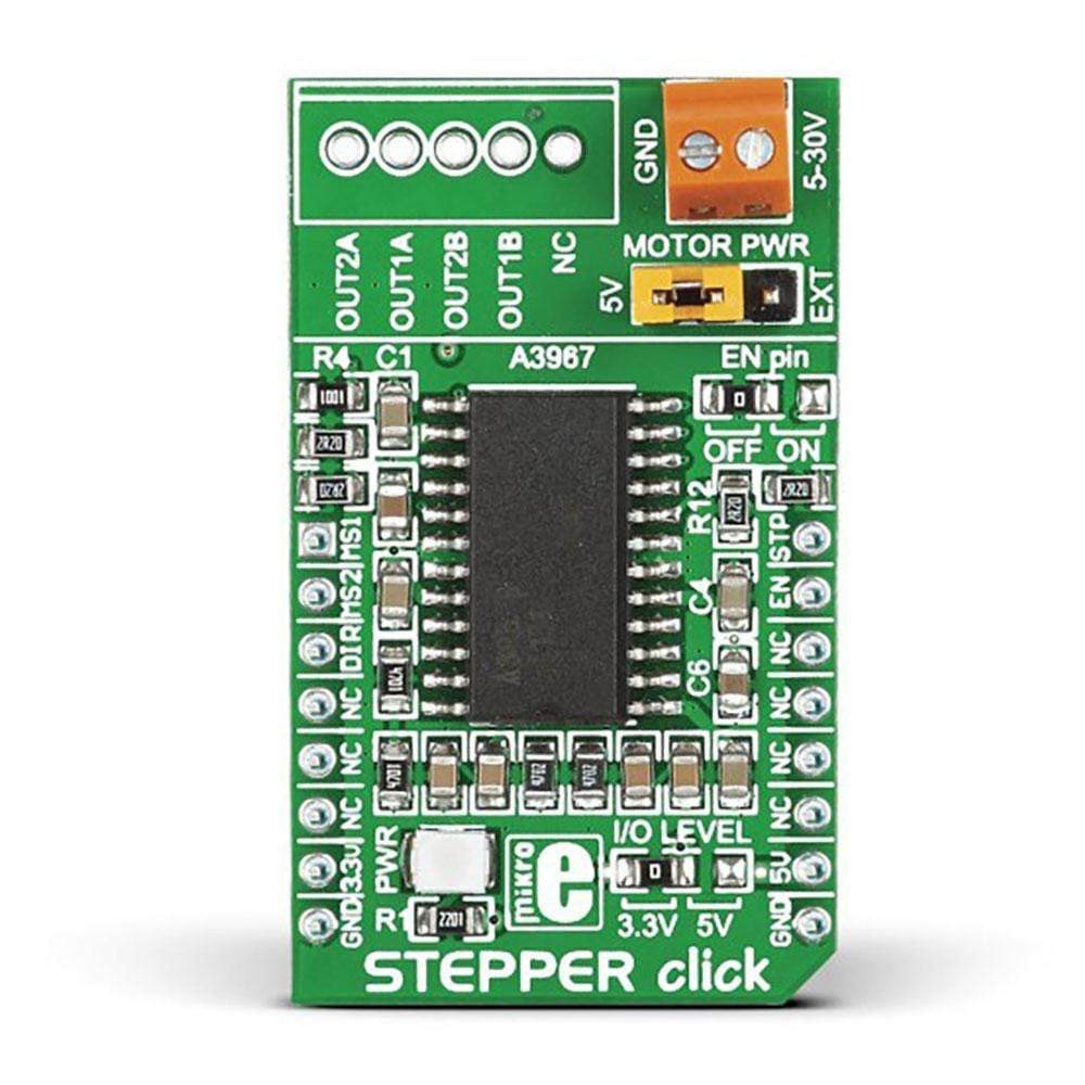
Introduce precision motor control to the user device with Stepper Click Board™. This stepper motor driver board includes an A3967SLBT stepper motor driver that allows controlling bipolar step motors in full-, half-, quarter- and eighth-step modes. The maximum output drive capability is 30V and nearly '500 mA.
It also features an integrated translator that supports the easy implementation of the A3967SLBT microstepping driver. The package is offered with two sets of connectors: a B5B-XH-A connector and a pair of screw terminals. Both types of connectors are delivered unsoldered with the package and can be used as a connecting option. The user can use the j3 jumper to select whether the power of the motor driver comes with the onboard or external power supply.
The Stepper Click Board™ supports either a 3.3V or 5V power supply, which can be selected through the zero-ohm J1 SMD jumper (3.3V is the default position). The user can also choose to use the motor driver.
Downloads
The Stepper Click Board™ is a complete solution for driving bipolar stepper motors with full/half and micro-steps. It features the A3967 IC from Allegro Microsystems with proprietary Satlington™ sink drivers on its outputs, which ensure high efficiency and reliable operation of the internal H-Bridges. This IC has the integrated translation section, used to simplify the control: using simple step control inputs from the host MCU, the stepper motor can be driven in both directions, with the predetermined step sizes. In addition, the output current is regulated allowing for noiseless operation of the stepper motor, with no resonance and ringing typically observed at unregulated stepper driver designs.
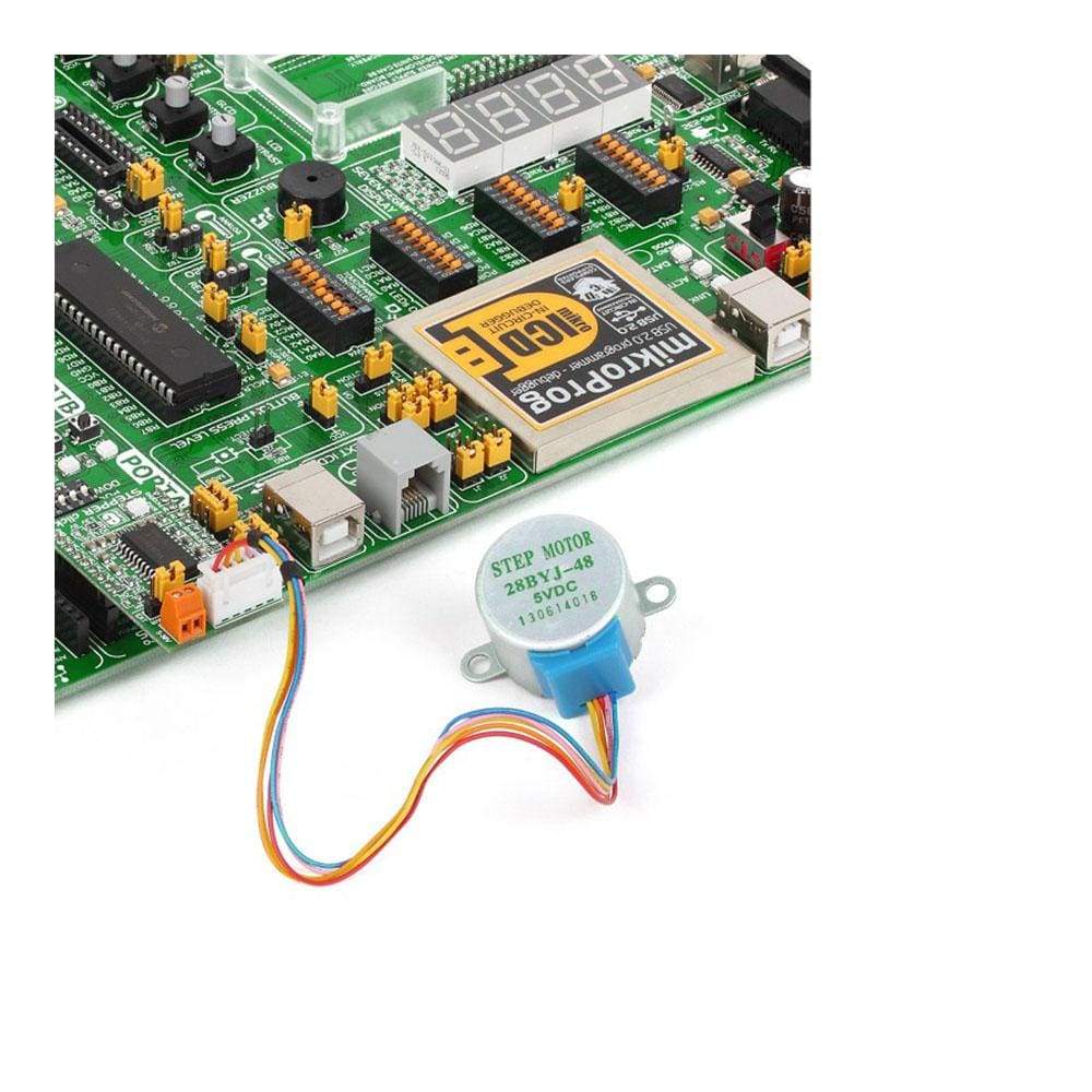
Additional features of the Stepper Click Board™ include undervoltage, shoot-through, and thermal protection, so the Click board™ can operate reliably. With its input voltage range up to 25V, it can drive a wide range of stepper motors with up to 750mA max. Due to simplicity of the step motor control, as well as the selection of various stepping modes offered by the Stepper Click Board™, it is a perfect solution for building various applications that require precise and reliable stepper motor control, such as the movement control of beds, heads, and assemblies of various CNC plotting, milling and 3D printer designs.
How Does The Stepper Click Board™ Work?
The Stepper Click Board™ uses the A3967, a micro-stepping driver IC with a translator, from Allegro Microsystems. This is a highly integrated IC, which offers a very simple bipolar stepper motor control interface, thanks to the integrated translator section. This section controls the output drivers, providing smooth action of the stepper motor. By controlling the current intensity throughout the rotation cycle, a constant torque is achieved for every position. The current regulator uses an internal comparator, DA converter, and external sensing resistor. The sensing resistor value determines the maximum current during the operation, limiting it to 568mA when using 5V, or to 350mA when using 3.3V as the reference voltage.
The reference voltage and the logic voltage levels can be selected by the I/O LEVEL selection SMD jumper. This jumper routes either 3.3V or 5V power rail from mikroBUS™ to LOG SUP and REF pins. LOG SUP pin is used as the power supply input for the logic section of the A3967 IC, while the voltage at the REF pin determines the reference voltage for the current regulator section. I/O LEVEL jumper allows the Click board™ to be interfaced to both 3.3V and 5V MCUs.
A LOW to HIGH transition on the STEP pin of the A3967 IC will perform one rotational step. The direction of the rotation is controlled by the logic state on the DIR pin. The step size is determined by two pins: MS1 and MS2. The truth table below provides a correlation between the logic states of these pins and the step size. It is possible to work with full step (using two phases), half step, quarter step, and eighth step. The STEP pin is routed to the mikroBUS™ PWM pin and it is labeled as STP. MS1 and MS2 pins are routed to the mikroBUS™ AN and RST pins respectively, labeled as MS1 and MS2. DIR pin is routed to the CS pin of the mikroBUS™ and it is labeled as DIR.
The SMD jumper labeled as EN pin can be used to route the #EN pin of the IC to the INT pin of the mikroBUS™. This allows the host MCU to enable or disable the A3967 IC. By default, this jumper is positioned to route the #EN pin to the GND directly, permanently enabling the IC.
The Stepper Click Board™ offers a choice to use a power source for driving the motor: one is the external voltage routed to the input connector, while the other is 5V power rail from the mikroBUS™. While using the external connector, the voltage of the external power supply should remain below 25V. Selection between the external power supply and 5V rail from the mikroBUS™ can be done by moving the jumper labeled as MOTOR PWR, to either 5V position or EXT position. This jumper is a 3x1 male header with the standard 2.54mm pitch, providing a simple and effortless operation.
The stepper motor can be connected via the disconnectable crimp style XH connector with 2.5mm pitch, which can be usually found on many small size stepper motors. This header is optional and comes unsoldered, in case that some other type of header or connector needs to be used, instead.
MICROSTEP RESOLUTION CONFIGURATION
| Step size: | Full | Half | 1/4 | 1/8 |
|---|---|---|---|---|
| MS1 | L | H | L | H |
| MS2 | L | L | H | H |
SPECIFICATIONS
| Type | Stepper |
| Applications | The Stepper Click Board™ is a perfect solution for building various applications that require a precise and reliable stepper motor control, such as the movement control of beds, heads, and assemblies of various CNC plotting, milling, and 3D printer designs. |
| On-board modules | A3967, a microstepping driver IC with a translator, from Allegro Microsystems, LLC. |
| Key Features | Integrated translation section used to simplify the control, proprietary Satlington™ sink drivers on the output stages, ability to run in full, half, quarter, eighth step, undervoltage and thermal protection, etc. |
| Interface | GPIO |
| Compatibility | mikroBUS |
| Click board size | M (42.9 x 25.4 mm) |
| Input Voltage | 3.3V or 5V |
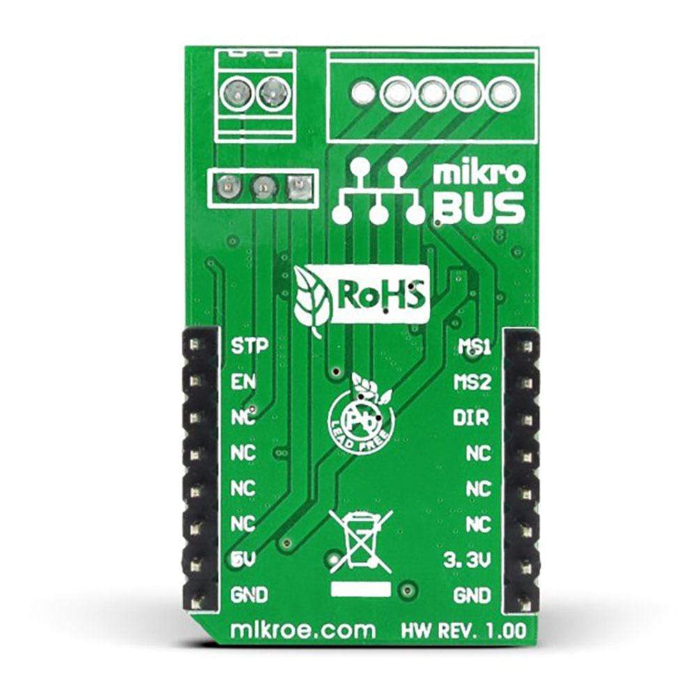
PINOUT DIAGRAM
This table shows how the pinout on the Stepper Click Board™ corresponds to the pinout on the mikroBUS™ socket (the latter shown in the two middle columns).
| Notes | Pin | Pin | Notes | ||||
|---|---|---|---|---|---|---|---|
| Step size bit 1 | MS1 | 1 | AN | PWM | 16 | STP | Step trigger |
| Step size bit 2 | MS2 | 2 | RST | INT | 15 | EN | Chip Enable |
| Direction | DIR | 3 | CS | RX | 14 | NC | |
| NC | 4 | SCK | TX | 13 | NC | ||
| NC | 5 | MISO | SCL | 12 | NC | ||
| NC | 6 | MOSI | SDA | 11 | NC | ||
| Power supply | +3.3V | 7 | 3.3V | 5V | 10 | +5V | Power Supply |
| Ground | GND | 8 | GND | GND | 9 | GND | Ground |
STEPPER CLICK ELECTRICAL SPECIFICATIONS
| Description | Min | Typ | Max | Unit |
|---|---|---|---|---|
| External power supply voltage | 5 | 5 | 25 | V |
| Current limit (min 3.3V/max 5V) | 375 | - | 560 | mA |
| Step size | Full | - | Eighth | step |
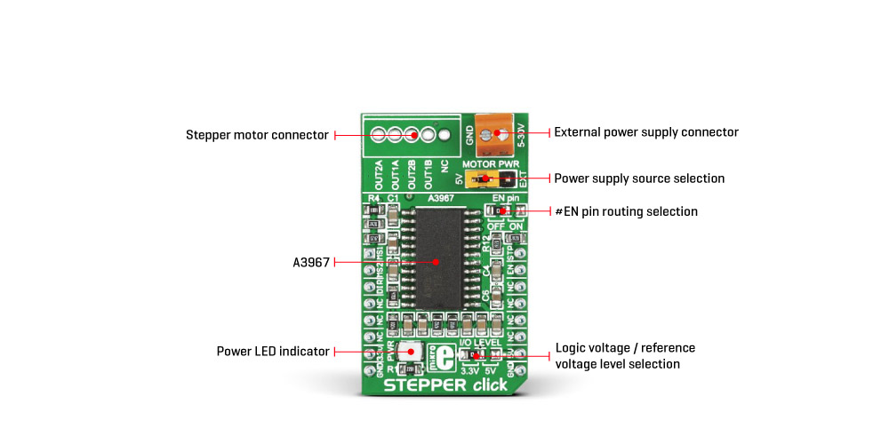
ONBOARD SETTINGS AND INDICATORS
| Label | Name | Default | Description |
|---|---|---|---|
| LD1 | PWR | - | Power LED indicator |
| J1A | I/O LEVEL | Left | LED driver voltage selection: left position 3.3V, right position 5V |
| J4A | EN Pin | Left | #EN Pin routing: OFF position - #EN pin routed to the GND, ON position - #EN pin routed to the mikroBUS™ INT pin |
| J3B | MOTOR PWM | Left | Motor power supply selection: left position - 5V rail from mikroBUS™, right position - external power supply |
| HD1 | 5-30V | - | External power supply connector |
| CN1 | - | - | 5-pole crimp style XH stepper motor connector (optional) |
| General Information | |
|---|---|
Part Number (SKU) |
MIKROE-1528
|
Manufacturer |
|
| Physical and Mechanical | |
Weight |
0.035 kg
|
| Other | |
EAN |
8606015075075
|
Frequently Asked Questions
Have a Question?
Be the first to ask a question about this.