Proximity 9 Click Board
Overview
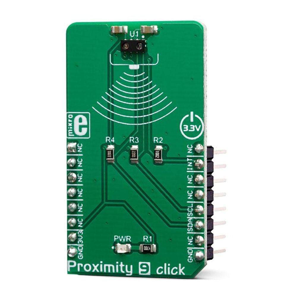
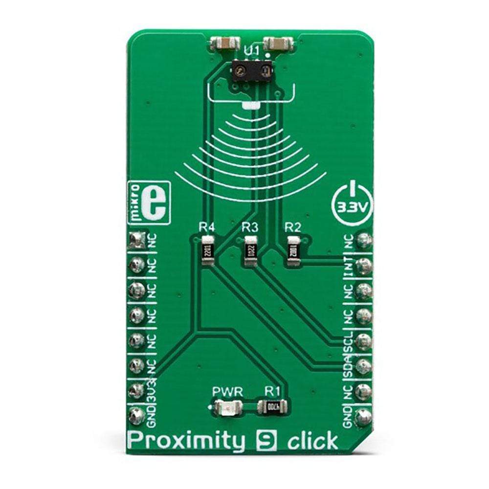
The Proximity 9 Click Board™ is a very accurate and reliable proximity sensing (PS) and ambient light sensing (ALS) device, equipped with the VCNL4040, an integrated PS and ALS sensor which features the Filtron™ technology. The 940nm infrared emitter, along with the low noise analogue front end, and the PS/ALS photo-sensitive elements, is integrated on the VCNL4040 IC, ensuring very accurate and reliable measurements.
The proprietary Filtron™ technology provides a response near to the human eye spectral response, providing the background light cancellation. The programmable interrupt engine allows for the development of an optimised firmware, reducing the MCU workload and power consumption.
The VCNL4040 also integrates some additional features for better reliability. It has an intelligent crosstalk cancelation scheme implemented, in order to reduce the crosstalk phenomenon. A smart persistence allows the interrupt engine to avoid false interrupt triggering. Rich with features, this Click board™ can be used for a range of different applications which rely on the accurate and reliable close proximity and ambient light sensing, including PC and laptop displays, POS displays, embedded displays, proximity-activated short-range security, lux meters, etc.
How Does The Proximity 9 Click Board™ Work?
The Proximity 9 Click Board™ features the VCNL4040, a fully integrated proximity and ambient light sensor with I2C interface, from Vishay Semiconductors. It is an advanced 16bit Ambient Light Sensor (ALS) which makes use of the proprietary Filtron™ technology, providing spectral response near to a human eye. The ALS sensor also helps with the flickering of fluorescent light sources, and background light cancellation, reducing the workload of the host MCU. This sensor features a 940 nm IRED on-chip, driven by a programmable current sink driver. The VCNL4040 is also thermally compensated, allowing very accurate readings within the range between -40⁰C and +85⁰C.
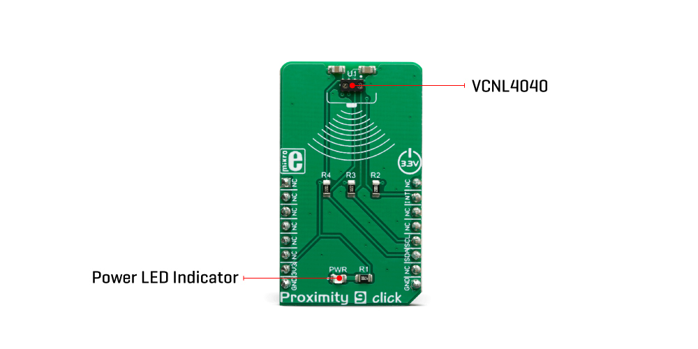
The Proximity Sensing (PS) section of the VCNL4040 IC implements several solutions for the improved proximity detection of objects of any color. It relies on the detection of the reflected IR light from the IRED emitter. Features such as the immunity to a red glow, intelligent crosstalk phenomenon reduction, smart persistence scheme for false interrupt triggering prevention, programmable IRED current, selectable sampling resolution, and selectable integration time, help achieving a reliable and accurate proximity detection. The processed readings of the ALS and PS sensors can be fetched from the respective registers via the I2C interface. The I2C bus lines are routed to the respective mikroBUS™ I2C pins: SCL is the I2C clock and SDA is the I2C data line.
The Proximity 9 Click Board™ offers programmable interrupt engine. The INT pin is routed to the mikroBUS™ INT pin and it is pulled up by the onboard resistor. When asserted, it is driven to a LOW logic level. The interrupt can be programmed to be triggered whenever PS threshold window is exceeded, for a programmed number of times (interrupt persistence). There are two interrupt modes: the interrupt will remain latched in the normal mode until the interrupt status flag is read by the host firmware. If set to a logic mode, the interrupt will be asserted when the PS value rises above the high threshold level, and de-asserted when the PS value falls below the low threshold level. The logic mode is useful when an autonomous operation with some external circuit is required, while the normal mode is best suited to be used with the MCU. The INT pin is routed to the INT pin of the mikroBUS™.
The Proximity 9 Click Board™ is supported by the mikroSDK library, which contains functions for simplified development. The mikroSDK functions are well-documented, but there is still a need, the datasheet of the VCNL4040 offers a listing of all the registers and their specific functions.
The Proximity 9 Click Board™ is designed to work with 3.3V only. When using it with MCUs that use 5V levels for their communication, a proper level translation circuit should be used.
Specifications
Type | Proximity |
Applications | The Proximity 9 Click Board™ can be used for a range of different applications which rely on the accurate and reliable close proximity and ambient light sensing, including PC and laptop displays, POS displays, embedded displays, proximity-activated short-range security, lux meters, etc. |
On-board modules | VCNL4040, an integrated proximity and ambient light sensor with I2C interface and interrupt function, by Vishay. |
Key Features | A reliable ambient light and proximity sensor IC featuring Filtron™ technology for realistic ambient light detection, immunity to red glow, crosstalk, and backlight interferences, immunity to light flickering, etc. |
Interface | I2C |
Compatibility | mikroBUS |
Click board size | M (42.9 x 25.4 mm) |
Input Voltage | 3.3V |
Pinout diagram
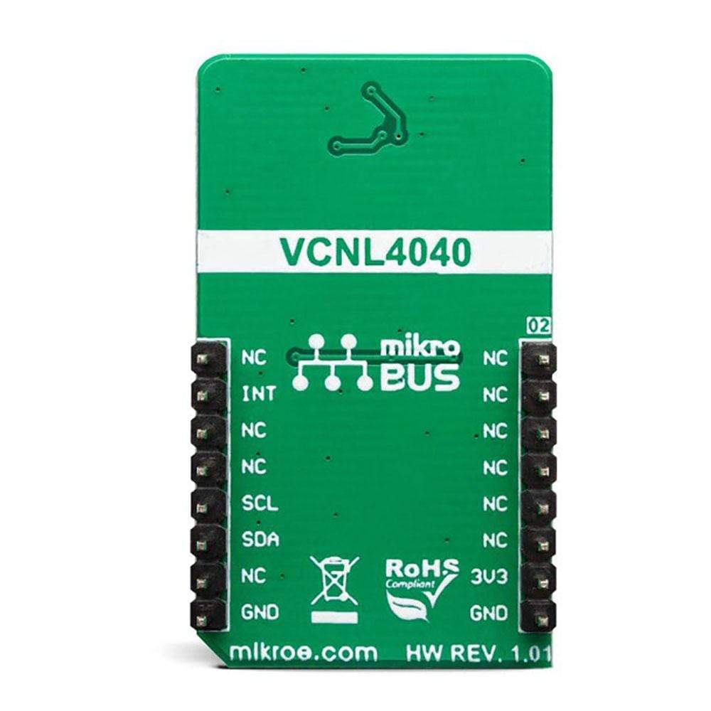
This table shows how the pinout on the Proximity 9 Click Board™ corresponds to the pinout on the mikroBUS™ socket (the latter shown in the two middle columns).
Notes | Pin | Pin | Notes | ||||
---|---|---|---|---|---|---|---|
NC | 1 | AN | PWM | 16 | NC | ||
NC | 2 | RST | INT | 15 | INT | Interrupt output | |
NC | 3 | CS | RX | 14 | NC | ||
NC | 4 | SCK | TX | 13 | NC | ||
NC | 5 | MISO | SCL | 12 | SCL | I2C Clock | |
NC | 6 | MOSI | SDA | 11 | SDA | I2C Data | |
Power Supply | 3.3V | 7 | 3.3V | 5V | 10 | NC | |
Ground | GND | 8 | GND | GND | 9 | GND | Ground |
Onboard settings and indicators
Label | Name | Default | Description |
---|---|---|---|
LD1 | PWR | - | Power LED indicator |
Software Support
We provide a library for the Proximity 9 Click Board™ on our LibStock page, as well as a demo application (example), developed using MikroElektronika compilers. The demo can run on all the main MikroElektronika development boards.
Library Description
This library allows user to get Proximity output data in the desired resolution and ALS output data calculated to lux. User also can configure the ALS sensitivity by changing the ALS integration time. This library also offers a choice to check a desired interrupt flags to be sure which interrupt is generated. For more details check documentation.
Key Functions
T_PROXIMITY9_RETVAL proximity9_readReg( uint8_t regAddr, uint16_t *dataOut )
- This function reads a 16bit data from the desired register.T_PROXIMITY9_RETVAL proximity9_writeReg( uint8_t regAddr, uint16_t dataIn )
- This function writes a 16bit data to the desired register.float proximity9_get_ALS_lux( void )
- This function allows user to get the ALS value calculated to lux.
Example Description
The application is composed of the three sections :
- System Initialization - Initializes peripherals and pins.
- Application Initialization - Initializes I2C interface and performs a device configurations.
- Application Task - (code snippet) - Performs a data reading and interrupt flag checking. Allows data and interrupt flags messages to be showed on the uart terminal. Note : The ALS sensitivity depends on the ALS integration time setting. The longer integration time has higher sensitivity. The Proximity (PS) output data can be set to 12-bit or 16-bit resolution.
void applicationTask() { als_data = proximity9_get_ALS_lux(); proximity9_readReg( _PROXIMITY9_PS_DATA_REG, &prox_data ); int_check = proximity9_check_int_flag( _PROXIMITY9_PS_IF_CLOSE_FLAG | _PROXIMITY9_PS_IF_AWAY_FLAG ); FloatToStr( als_data, text ); mikrobus_logWrite( "** ALS : ", _LOG_TEXT ); mikrobus_logWrite( text, _LOG_TEXT ); mikrobus_logWrite( " lux", _LOG_LINE ); WordToStr( prox_data, text ); mikrobus_logWrite( "** PROXIMITY : ", _LOG_TEXT ); mikrobus_logWrite( text, _LOG_LINE ); if (int_check == _PROXIMITY9_PS_IF_CLOSE_FLAG) { mikrobus_logWrite( "** Object is close!", _LOG_LINE ); mikrobus_logWrite( "************************************", _LOG_LINE ); Sound_Play( 1200, 50 ); Delay_ms( 50 ); Sound_Play( 1200, 50 ); Delay_ms( 50 ); Sound_Play( 1200, 50 ); } if (int_check == _PROXIMITY9_PS_IF_AWAY_FLAG) { mikrobus_logWrite( "** Object is away!", _LOG_LINE ); mikrobus_logWrite( "************************************", _LOG_LINE ); Sound_Play( 1100, 100 ); Delay_ms( 50 ); Sound_Play( 1100, 100 ); } if (int_check == _PROXIMITY9_INT_CLEARED) { mikrobus_logWrite( "************************************", _LOG_LINE ); Delay_ms( 200 ); } }
The full application code, and ready to use projects can be found on our LibStock page.
Other mikroE Libraries used in the example:
I2C
UART
Conversions
Sound
Additional Notes and Information
Depending on the development board you are using, you may need a USB UART click, USB UART 2 click or RS232 click to connect to your PC, for development systems with no UART to USB interface available on the board. The terminal available in all MikroElektronika compilers, or any other terminal application of your choice, can be used to read the message.
mikroSDK
The Proximity 9 Click Board™ is supported with mikroSDK - MikroElektronika Software Development Kit. To ensure proper operation of mikroSDK compliant click board demo applications, mikroSDK should be downloaded from the LibStock and installed for the compiler you are using.
Frequently Asked Questions
Have a Question?
Be the first to ask a question about this.