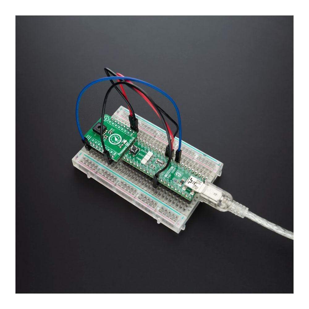
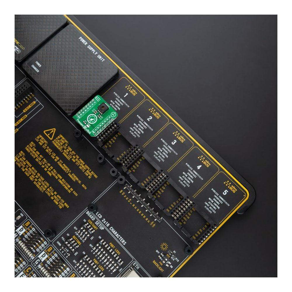
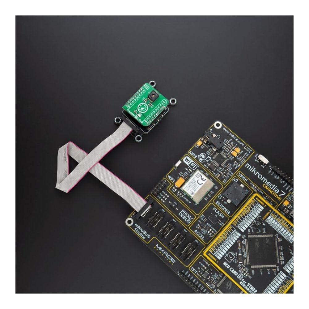
Overview
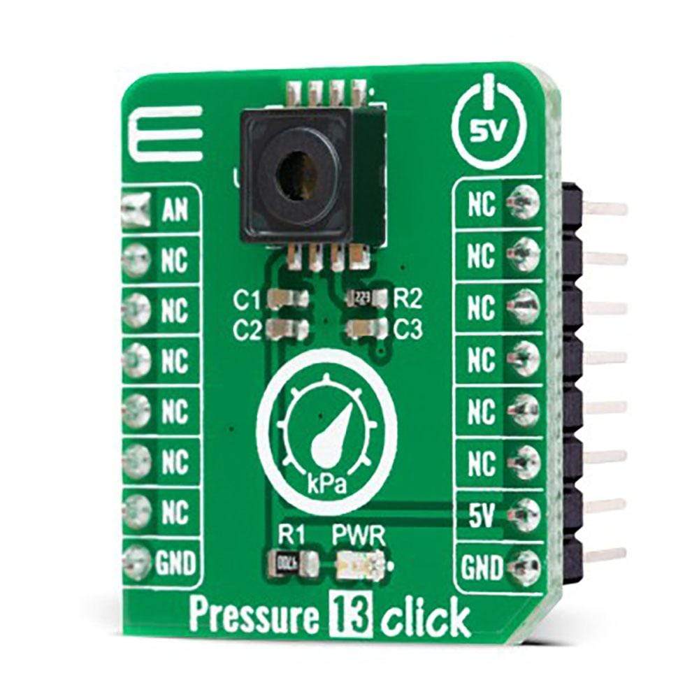
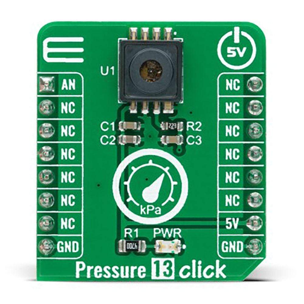
The Pressure 13 Click Board™ is a compact add-on board that contains an integrated pressure sensor for manifold air pressure measurement applications. This board features the KP229E2701, a miniaturized analogue manifold air pressure sensor based on a capacitive principle from Infineon. This sensor converts the pressure of 10 kPa to 300 kPa into an analogue output signal, a voltage range of 0.40 V to 4.65 V. Also, the manifold pressure data can be used to compute diagnostics of leakages and malfunctions of the exhaust gas recirculation valve. The high accuracy and the high sensitivity of the KP229E2701 make this Click Board™ a perfect choice for advanced automotive applications as well as in industrial and consumer applications.
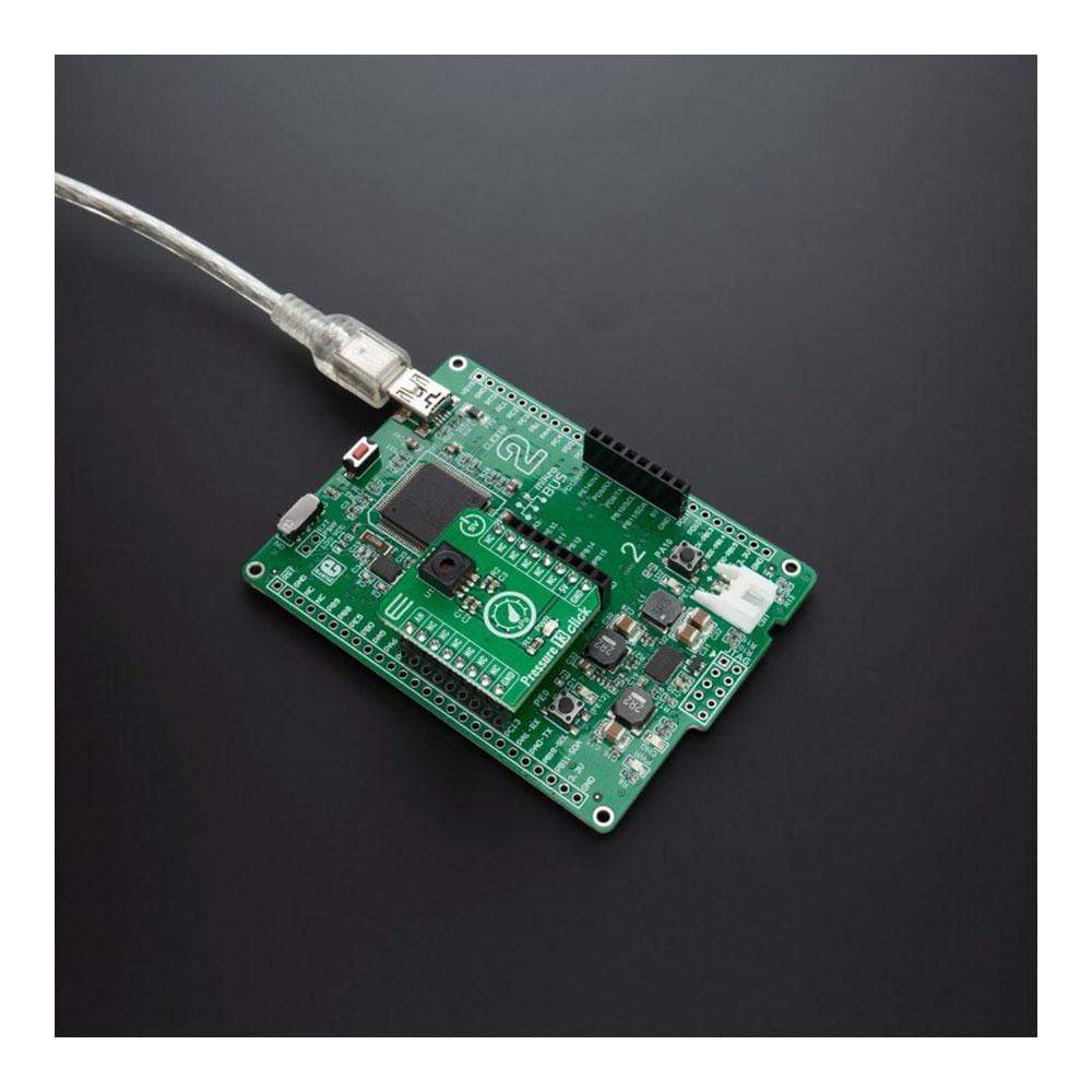
The Pressure 13 Click is supported by a mikroSDK compliant library, which includes functions that simplify software development. This Click Board™ comes as a fully tested product, ready to be used on a system equipped with the mikroBUS™ socket.
Downloads
How Does The Pressure 13 Click Board™ Work?
The Pressure 13 Click Board™ is based on the KP229E2701, a miniaturized analog absolute pressure sensor based on a capacitive principle from Infineon. The pressure is detected by an array of capacitive surface micromachined sensor cells (a monolithic integrated signal conditioning circuit implemented in BiCMOS technology). The sensor cell output is amplified, temperature compensated, and linearized to obtain an output voltage that is proportional to the applied pressure. The manifold air pressure (MAP) is a principal parameter to compute the air-fuel ratio provided to the engine for lower emission due to better combustion and increased efficiency. For cost-sensitive engine systems, a MAP sensor shows the potential to complement or even substitute mass airflow (MAF) sensors.
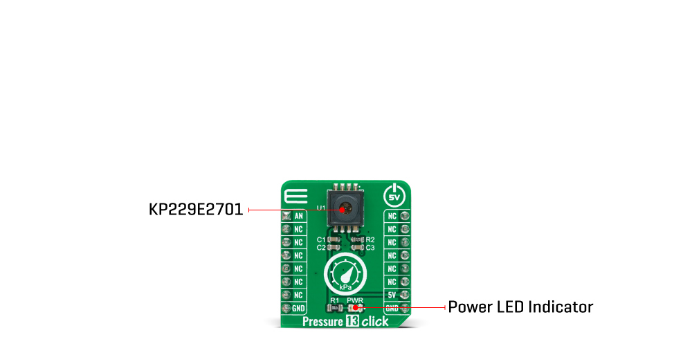
The accuracy of the KP229E2701 sensor is influenced by the supply voltage (ratiometric error) as well as by pressure, temperature, and aging effects. All parameters needed for the complete calibration algorithm - such as offset, gain, temperature coefficients of offset and gain, and linearization parameters - are determined after the assembly. These parameters are stored in an integrated E²PROM protected with forwarding error correction (a one-bit error is detected and corrected, errors of more than one bit are detected, and the output signal is switched to ground potential).
In automotive applications where high production volumes are custom, there is substantial interest in precision, low-cost, and fully integrated sensors. That's why the manifold pressure data can be used to compute diagnostics of leakages and malfunctions of the exhaust gas recirculation valve.
The Pressure 13 Click Board™ communicates with MCU using only one GPIO pin routed on the AN pin of the mikroBUS™ socket. The KP229E2701 sensor possesses several digital pins used only during calibration and test. That's why it's recommended and done to leave these pins floating. The output circuit acts as a low-pass decoupling filter between the sensor output and the A/D input of the MCU because it's recommended to protect the pressure sensor against overload and electromagnetic interferences.
The Pressure 13 Click Board™ is designed to be operated only with a 5V logic voltage level. A proper logic voltage level conversion should be performed before the Click board™ is used with MCUs with different logic levels. However, the Click board™ comes equipped with a library that contains easy to use functions and an example code that can be used as a reference for further development.
SPECIFICATIONS
| Type | Pressure |
| Applications | Can be used for advanced automotive applications as well as in industrial and consumer applications. |
| On-board modules | The Pressure 13 Click Board™ is based on the KP229E2701, a miniaturized analog absolute pressure sensor based on a capacitive principle from Infineon. |
| Key Features | Low power consumption, high precision pressure sensing (± 2.5 kPa), ratiometric analog output, large temperature range, automotive qualified, and more. |
| Interface | Analog |
| Compatibility | mikroBUS |
| Click board size | S (28.6 x 25.4 mm) |
| Input Voltage | 5V |
PINOUT DIAGRAM
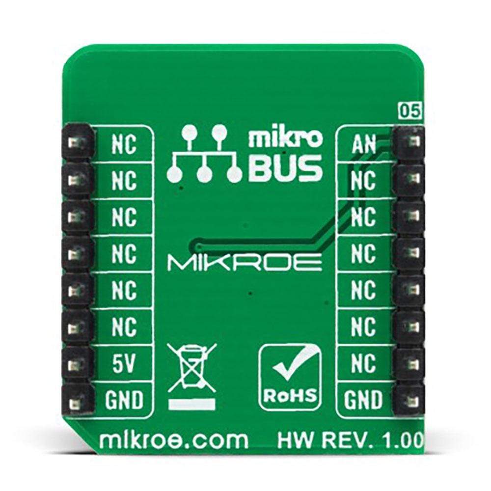
This table shows how the pinout on Pressure 13 Click corresponds to the pinout on the mikroBUS™ socket (the latter shown in the two middle columns).
| Notes | Pin |  |
Pin | Notes | |||
|---|---|---|---|---|---|---|---|
| Analog Pressure Signal Output |
AN | 1 | AN | PWM | 16 | NC | |
| NC | 2 | RST | INT | 15 | NC | ||
| NC | 3 | CS | RX | 14 | NC | ||
| NC | 4 | SCK | TX | 13 | NC | ||
| NC | 5 | MISO | SCL | 12 | NC | ||
| NC | 6 | MOSI | SDA | 11 | NC | ||
| NC | 7 | 3.3V | 5V | 10 | 5V | Power Supply | |
| Ground | GND | 8 | GND | GND | 9 | GND | Ground |
ONBOARD SETTINGS AND INDICATORS
| Label | Name | Default | Description |
|---|---|---|---|
| LD1 | PWR | - | Power LED Indicator |
PRESSURE 13 CLICK ELECTRICAL SPECIFICATIONS
| Description | Min | Typ | Max | Unit |
|---|---|---|---|---|
| Supply Voltage | 4.5 | - | 5.5 | V |
| Ambient Operating Pressure Range | 10 | - | 300 | kPa |
| Accuracy | - | ±3.75 | - | kPa |
| Maximum Output Current | -1 | - | 1 | mA |
| Analog Output Voltage | 0.4 | - | 4.65 | V |
| Operating Temperature Range | -40 | - | 140 | °C |
| General Information | |
|---|---|
Part Number (SKU) |
MIKROE-4294
|
Manufacturer |
|
| Physical and Mechanical | |
Weight |
0.017 kg
|
| Other | |
Country of Origin |
|
HS Code Customs Tariff code
|
|
EAN |
8606027380754
|
Warranty |
|
Frequently Asked Questions
Have a Question?
Be the first to ask a question about this.


