Key Features
Overview
Introducing the Step Down 5 Click Board™: High-Efficiency Voltage Conversion Made Easy
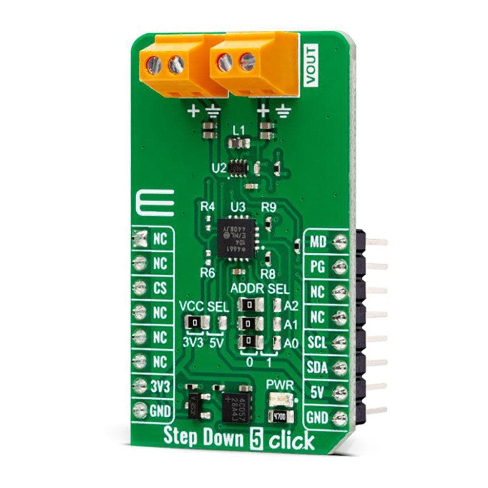
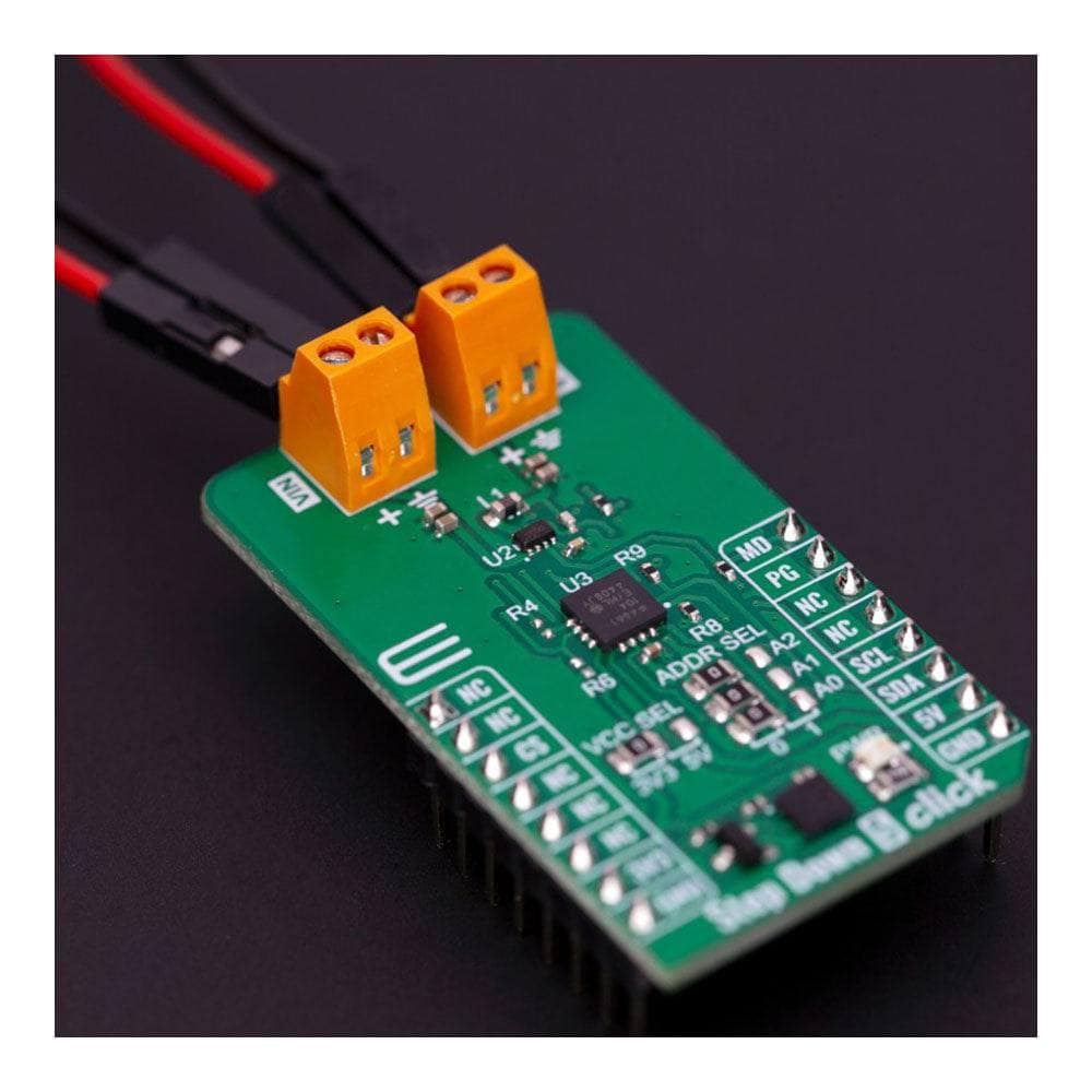
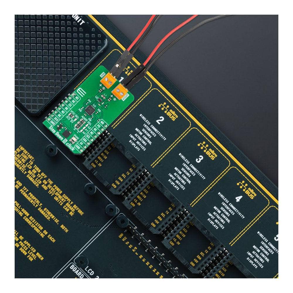
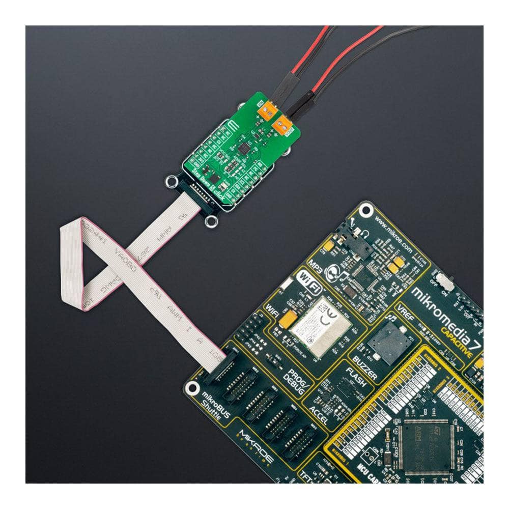
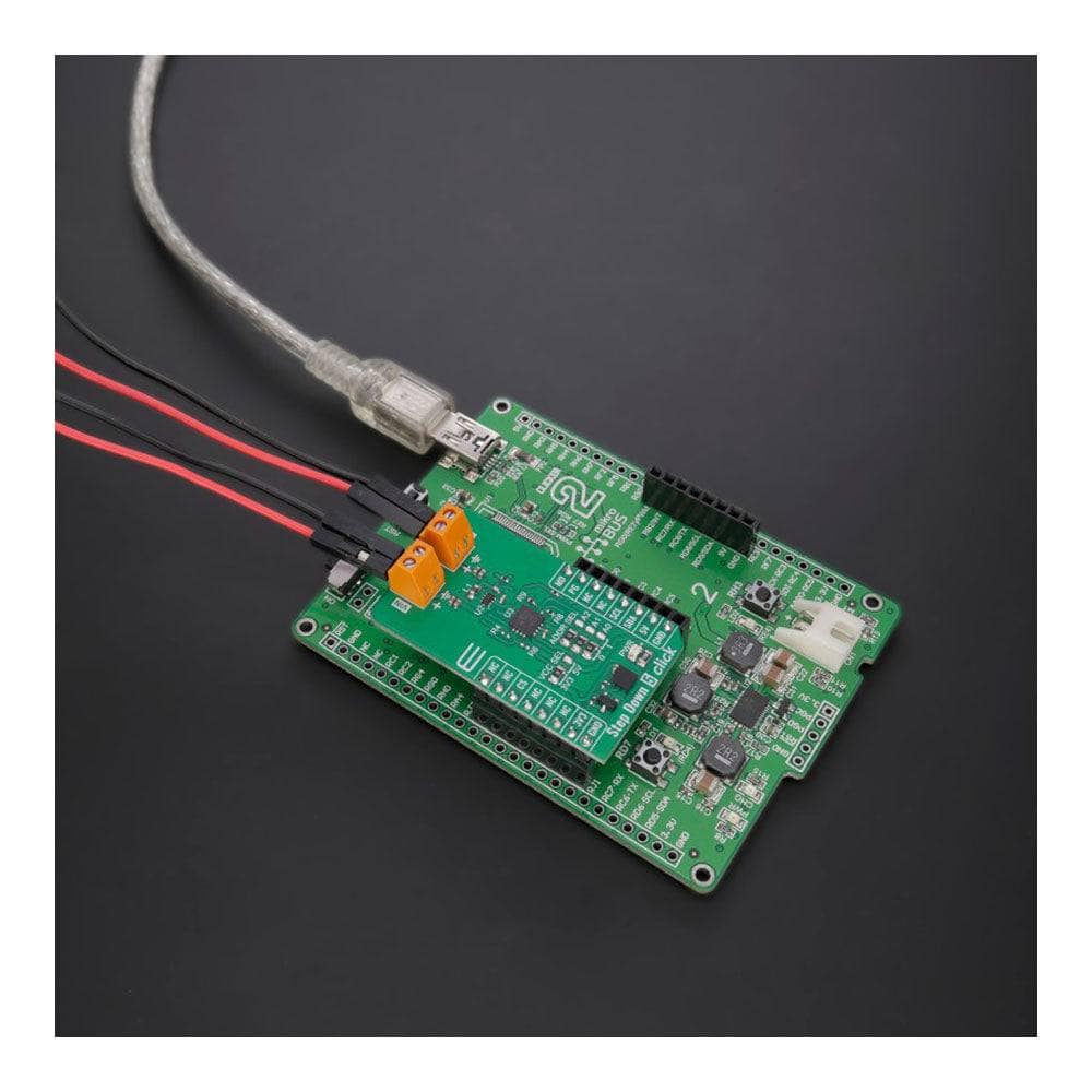
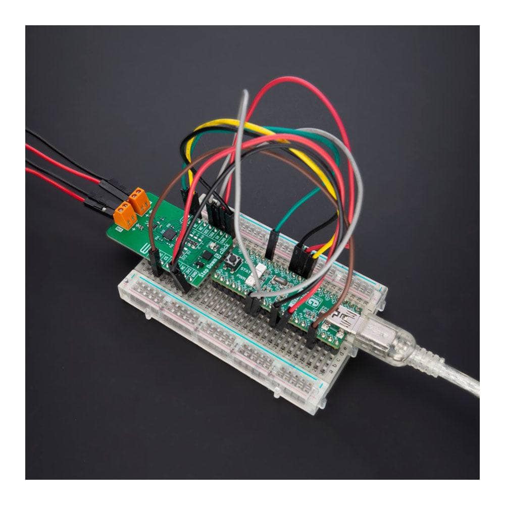
Discover the power of the Step Down 5 Click Board™, a compact and efficient add-on board that effortlessly converts higher voltage levels to lower ones. This incredible board features the TPS628510, a top-notch synchronous step-down DC/DC converter from Texas Instruments. Specifically designed for applications where high efficiency is essential, the TPS628510 delivers up to 500mA output current and operates with input voltages ranging from 2.7V to 6V.
Advanced Features for Optimal Performance
Experience the flexibility of the Step Down 5 Click Board™ with its 2.25MHz fixed switching frequency, selectable forced-PWM or PWM/PFM mode of operation, and adjustable output voltage from 0.6V to 5.5V, all set via an I2C-configurable digital potentiometer. Moreover, the board features a Power Good signal to indicate a stabilized output voltage, ensuring your voltage conversion is accurate and reliable.
Perfect for a Wide Range of Applications
From automation and control applications to industrial sensors, test and measurement equipment, and portable low-power devices, the Step Down 5 Click Board™ is the perfect solution for all your power conversion needs.
Seamless Integration with mikroSDK
Supported by a mikroSDK-compliant library, the Step Down 5 Click Board™ simplifies software development with a suite of functions designed for your convenience. As a fully tested product, this Click board™ is ready to be used with any system equipped with the mikroBUS™ socket, making voltage conversion easier than ever before.
Downloads
How Does The Step Down 5 Click Board™Work?
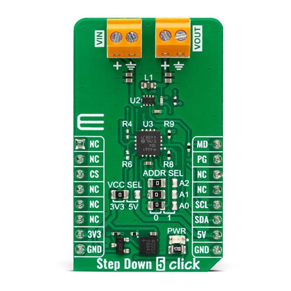
The Step Down 5 Click Board™ is based on the TPS628510, a synchronous step-down converter from Texas Instruments, providing interface-configurable output voltage range from 0.6V to 5.5V suitable for point-of-load and post-regulation applications. This synchronous switch mode power converter is based on a peak current mode control topology and achieves fast and stable operation with an internally compensated control loop. It provides up to 0.5A load current over a wide input supply range from 2.7V to 6V and has excellent load and line regulation. In addition, it is characterized by high efficiency over a wide range of load output voltage from 0.6V to 5.5V, which can be easily adjusted using a digital potentiometer, the MCP4661 from Microchip.
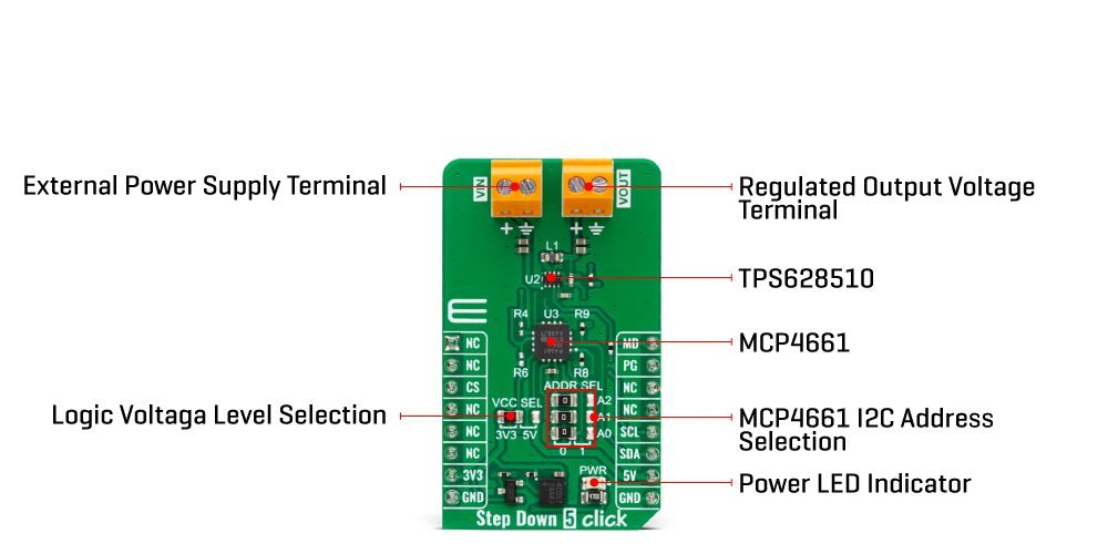
The TPS628510 supports forced fixed frequency PWM operation with the MD pin of the mikroBUS™ socket set to a high logic level. Its switching frequency is internally fixed at 2.25MHz. When the MD pin is set to a low logic level, the TPS628510 operates in power save mode (PFM) at a low output current and automatically transfers to fixed-frequency PWM mode at a higher output current. In PFM mode, the switching frequency decreases linearly based on the load to sustain high efficiency down to a very low output current. Alternatively, the TPS628510 can be synchronized to an external clock signal from 1.8MHz to 4MHz, applied to the MD pin. An internal PLL allows you to change from an internal clock to an external clock during operation.
Besides the operational mode selection pin, this Click board™ also has a power-good function routed to the PG pin of the mikroBUS™ socket, indicating that the output reached desired regulation and the possibility for the MCP4661 to choose the least significant bit (LSB) of its I2C slave address by positioning SMD jumpers labelled as ADDR SEL to an appropriate position marked as 0 and 1.
The Step Down 5 Click Board™ can operate with either 3.3V or 5V logic voltage levels selected via the VCC SEL jumper. This way, both 3.3V and 5V capable MCUs can use the communication lines properly. However, the Click board™ comes equipped with a library containing easy-to-use functions and an example code that can be used, as a reference, for further development.
SPECIFICATIONS
| Type | Buck |
| Applications | It can be used for power conversion solutions in automation and control applications, industrial sensors, test and measurement equipment, portable low-power devices, and more |
| On-board modules | TPS628510 - synchronous step-down converter from Texas Instruments |
| Key Features | Based on a peak current mode control topology, output current up to 0.5A, selectable output voltage via digital potentiometer, high accuracy and efficiency, fixed switching frequency, forced PWM or PWM/PFM operation, power good indicator, and more |
| Interface | I2C,PWM |
| Compatibility | mikroBUS |
| Click board size | M (42.9 x 25.4 mm) |
| Input Voltage | 3.3V or 5V |
PINOUT DIAGRAM
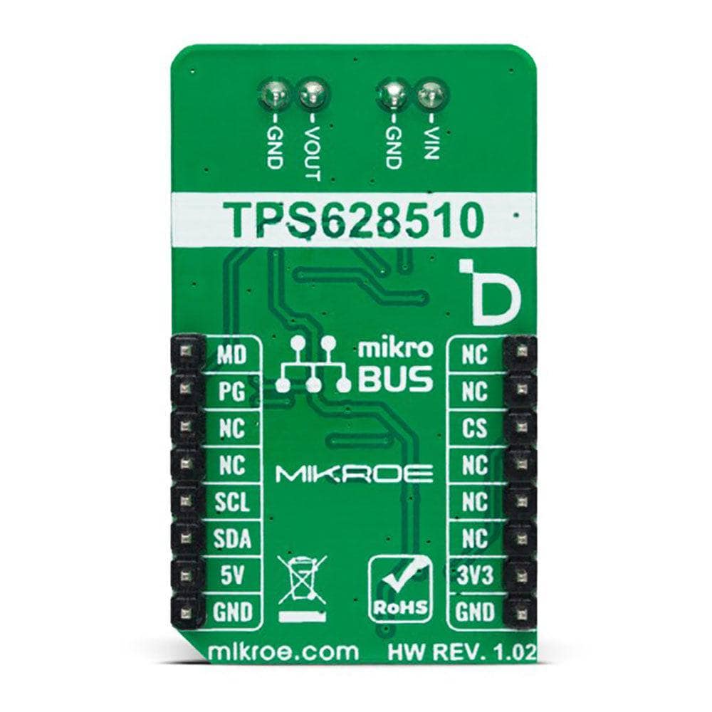
This table shows how the pinout of the Step Down 5 Click Board™ corresponds to the pinout on the mikroBUS™ socket (the latter shown in the two middle columns).
| Notes | Pin |  |
Pin | Notes | |||
|---|---|---|---|---|---|---|---|
| NC | 1 | AN | PWM | 16 | MD | Mode Selection | |
| NC | 2 | RST | INT | 15 | PG | Power-Good Indicator | |
| NC | 3 | CS | RX | 14 | NC | ||
| NC | 4 | SCK | TX | 13 | NC | ||
| NC | 5 | MISO | SCL | 12 | SCL | I2C Clock | |
| NC | 6 | MOSI | SDA | 11 | SDA | I2C Data | |
| Power Supply | 3.3V | 7 | 3.3V | 5V | 10 | 5V | Power Supply |
| Ground | GND | 8 | GND | GND | 9 | GND | Ground |
ONBOARD SETTINGS AND INDICATORS
| Label | Name | Default | Description |
|---|---|---|---|
| LD1 | PWR | - | Power LED Indicator |
| JP1 | VCC SEL | Left | Logic Level Voltage Selection 3V3/5V: Left position 3V3, Right position 5V |
| JP2-JP4 | ADDR SEL | Left | I2C Address Selection 0/1: Left position 0, Right position 1 |
STEP DOWN 5 CLICK ELECTRICAL SPECIFICATIONS
| Description | Min | Typ | Max | Unit |
|---|---|---|---|---|
| Supply Voltage | 3.3 | - | 5 | V |
| External Supply Voltage | 2.7 | - | 6 | V |
| Output Voltage | 0.6 | - | 5.5 | V |
| Output Current | - | - | 0.5 | A |
| General Information | |
|---|---|
Part Number (SKU) |
MIKROE-5572
|
Manufacturer |
|
| Physical and Mechanical | |
Weight |
0.02 kg
|
| Other | |
Country of Origin |
|
HS Code Customs Tariff code
|
|
EAN |
8606027384622
|
Warranty |
|
Frequently Asked Questions
Have a Question?
-
What software development support is available for the Step Down 5 Click Board™?
The Step Down 5 Click Board™ is supported by a mikroSDK-compliant library, which includes functions that simplify software development.
-
What applications is the Step Down 5 Click Board™ suitable for?
The Step Down 5 Click Board™ is suitable for power conversion solutions in various applications, including automation and control, industrial sensors, test and measurement equipment, and portable low-power devices.
-
What are the features of the Step Down 5 Click Board™?
The Step Down 5 Click Board™ has several features, including: 1) The ability to convert higher voltages into lower voltages 2) A TPS628510 DC/DC converter 3) The ability to provide up to 500mA output current 4) Input voltage ranging from 2.7V to 6V 5) Fixed switching frequency of 2.25MHz 6) Selectable output voltage from 0.6V to 5.5V 7) Power Good signal to indicate stabilized output voltage
-
What is the TPS628510?
The TPS628510 is a DC/DC converter from Texas Instruments that can provide up to 500mA output current with an input voltage ranging from 2.7V to 6V. It is specifically designed for applications where high efficiency is crucial and has a switching frequency of 2.25MHz.
-
What is the Step Down 5 Click Board™?
The Step Down 5 Click Board™ is an add-on board that can convert a higher voltage into a lower voltage level. It features the TPS628510, a high-efficiency, easy-to-use, synchronous step-down DC/DC converter from Texas Instruments.

