Key Features
Overview
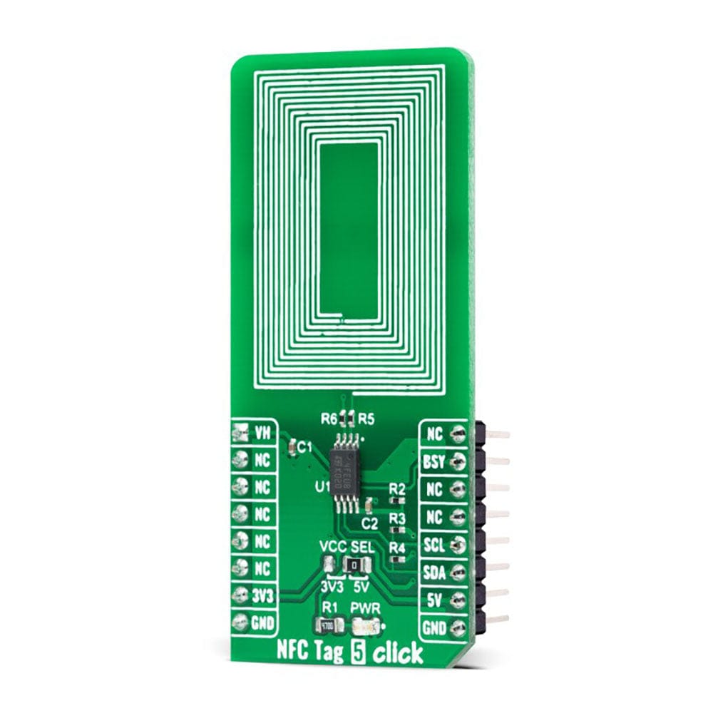
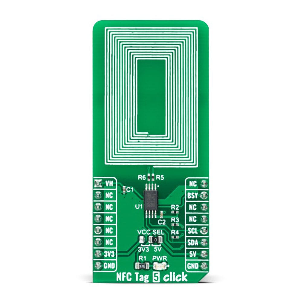
The NFC Tag 5 Click Board™ is a compact add-on board that contains a compact NFC tag IC. This board features the M24LR64E-R, a dynamic NFC/RFID tag IC with a dual interface 64-Kbit EEPROM from STMicroelectronics. It features an I2C interface alongside an RF contactless interface operating at 13.56MHz, organized as 8192×8 bits in the I2C mode and 2048×32 bits in the ISO 15693 and ISO 18000-3 mode 1 RF mode. The M24LR64E-R also features an energy harvesting analogue output and a user-configurable digital output pin, used as an interrupt, toggling during either RF write in progress or RF busy mode. This Click board™ represents an ideal solution for rapidly integrating NFC tag technology in any custom application such as industrial or medical equipment, consumer electronics, and more.
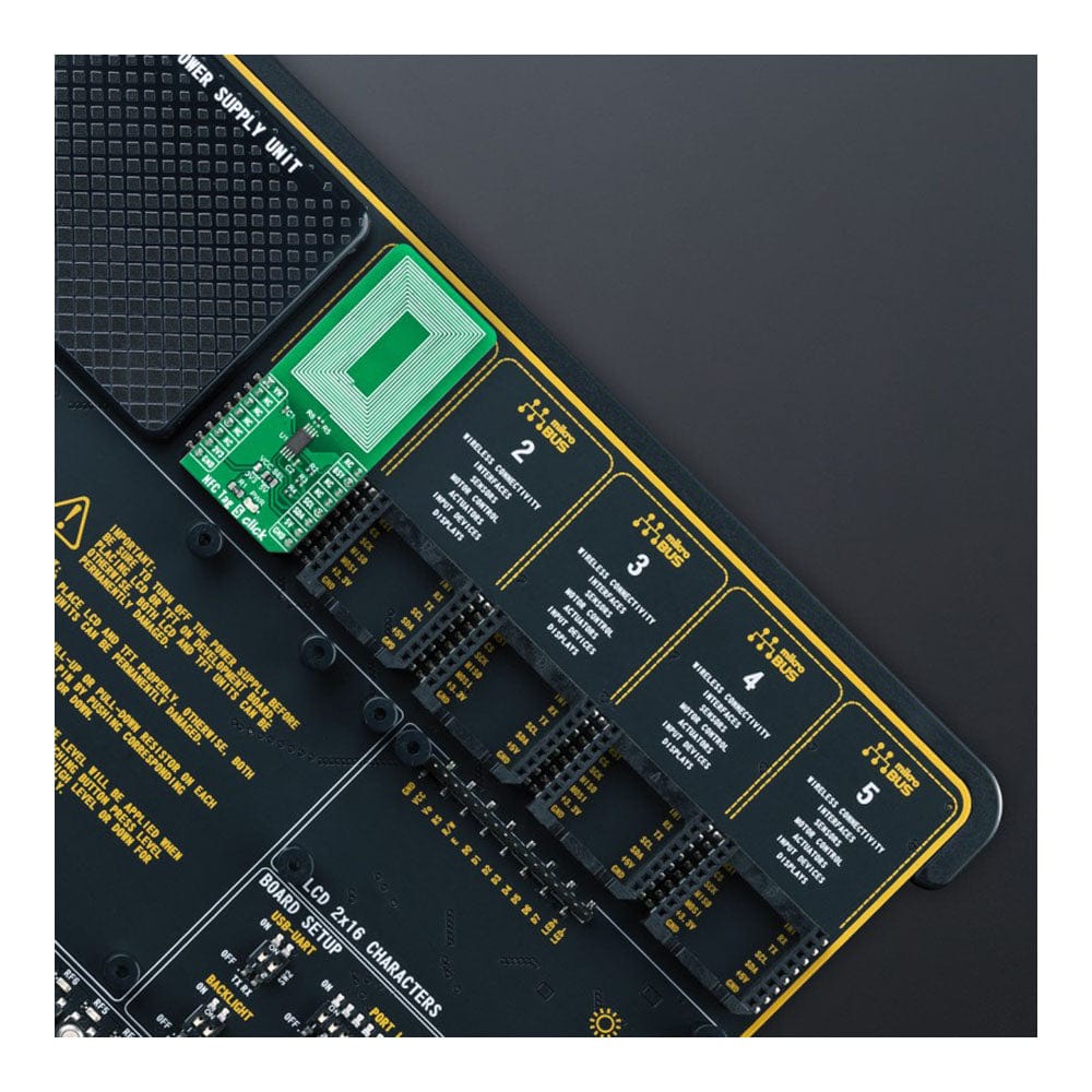
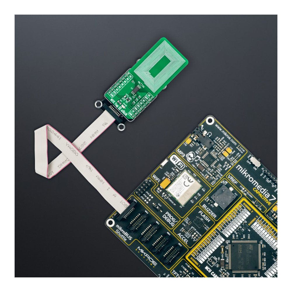
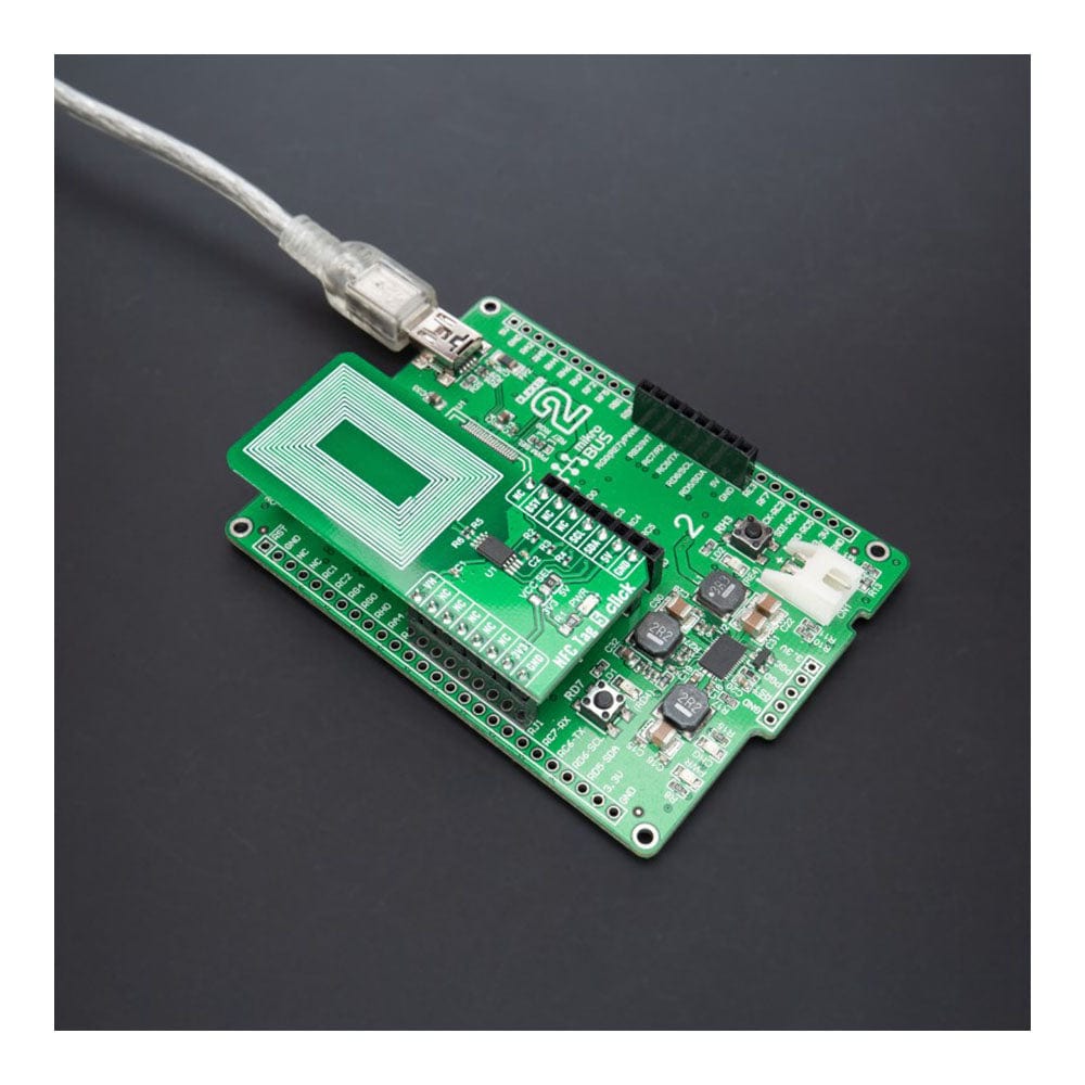
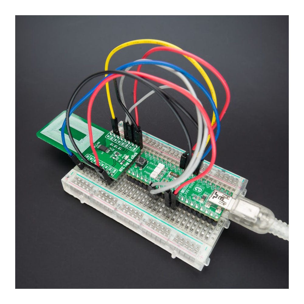
The NFC Tag 5 Click Board™ is supported by a mikroSDK compliant library, including functions that simplify software development. This Click board™ comes as a thoroughly tested product, ready to be used on a system equipped with the mikroBUS™ socket.
Downloads
How Does The Work?
The NFC Tag 5 Click Board™ is based on the the M24LR64E-R, a 64-Kbit dynamic NFC/RFID tag with password protection, energy harvesting, and RF status functions from STMicroelectronics. This highly integrated Near Field Communication tag module comes with a dual-interface electrically erasable programmable memory (EEPROM), an I2C interface alongside an RF contactless interface operating at 13.56MHz, organized as 8192×8 bits in the I2C mode and 2048×32 bits in the ISO 15693 and ISO 18000-3 mode 1 RF mode.
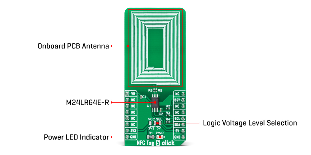
The NFC Tag 5 Click Board™ contains the properly tuned integrated trace antenna on the PCB to power and access the device using the ISO/IEC 15693 and ISO 18000-3 mode 1 protocol. Power is transferred to the M24LR64E-R by radio frequency at 13.56MHz via coupling antennas.
As mentioned before, this Click board™ communicates with MCU using the standard I2C 2-Wire interface with a maximum clock frequency of 400kHz, fully adjustable through software registers. It also provides an Energy harvesting mode on the analog pin of the mikroBUS™ socket marked as VH. When the Energy harvesting mode is activated, the M24LR64E-R can output the excess energy from the RF field on the VH pin. If the RF field strength is insufficient or when the Energy harvesting mode is disabled, the VH pin goes into a high-Z state, and the Energy harvesting mode is automatically stopped.
Besides, it also features a user-configurable pin marked as BSY, routed to the AN analog pin of the mikroBUS™ socket, used either to indicate that the M24LR64E-R is executing an internal write cycle from the RF channel or that an RF command is in progress. When configured in the RF write in progress mode, the BSY pin is driven low for the entire duration of the RF internal write operation, and when configured in the RF busy mode, this pin is driven low for the whole period of the RF command progress.
The NFC Tag 5 Click Board™ can operate with both 3.3V and 5V logic voltage levels selected via the VCC SEL jumper. This way, it is allowed for both 3.3V and 5V capable MCUs to use the communication lines properly. However, the Click board™ comes equipped with a library containing easy-to-use functions and an example code that can be used, as a reference, for further development.
SPECIFICATIONS
| Type | RFID/NFC |
| Applications | Can be used in any custom application such as industrial or medical equipment, consumer electronics, and more |
| On-board modules | M24LR64E-R - dynamic NFC/RFID tag IC from STMicroelectronics |
| Key Features | Dual interface (I2C interface and RF contactless) 64-Kbit EEPROM, password protection, energy harvesting, and RF status functions, ISO 15693 and ISO 18000-3 mode 1 compatible, and more |
| Interface | Analog,I2C |
| Compatibility | mikroBUS |
| Click board size | L (57.15 x 25.4 mm) |
| Input Voltage | 3.3V or 5V |
PINOUT DIAGRAM
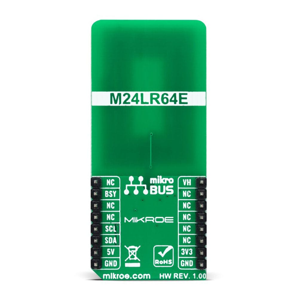
This table shows how the pinout of the NFC Tag 5 Click Board™ corresponds to the pinout on the mikroBUS™ socket (the latter shown in the two middle columns).
| Notes | Pin |  |
Pin | Notes | |||
|---|---|---|---|---|---|---|---|
| Energy Harvest | VH | 1 | AN | PWM | 16 | NC | |
| NC | 2 | RST | INT | 15 | BSY | RF Status | |
| NC | 3 | CS | RX | 14 | NC | ||
| NC | 4 | SCK | TX | 13 | NC | ||
| NC | 5 | MISO | SCL | 12 | SCL | I2C Clock | |
| NC | 6 | MOSI | SDA | 11 | SDA | I2C Data | |
| Power Supply | 3.3V | 7 | 3.3V | 5V | 10 | 5V | Power Supply |
| Ground | GND | 8 | GND | GND | 9 | GND | Ground |
ONBOARD SETTINGS AND INDICATORS
| Label | Name | Default | Description |
|---|---|---|---|
| LD1 | PWR | - | Power LED Indicator |
| JP1 | VCC SEL | Right | Logic Level Voltage Selection 3V3/5V: Left position 3V3, Right position 5V |
NFC TAG 5 CLICK ELECTRICAL SPECIFICATIONS
| Description | Min | Typ | Max | Unit |
|---|---|---|---|---|
| Supply Voltage | 3.3 | - | 5 | V |
| External RF Signal Frequency | - | 13.56 | - | MHz |
| EEPROM Size | - | 64 | - | kBit |
| Operating Temperature Range | -40 | +25 | +85 | °C |
| General Information | |
|---|---|
Part Number (SKU) |
MIKROE-5230
|
Manufacturer |
|
| Physical and Mechanical | |
Weight |
0.02 kg
|
| Other | |
Country of Origin |
|
HS Code Customs Tariff code
|
|
EAN |
8606027388262
|
Warranty |
|
Frequently Asked Questions
Have a Question?
Be the first to ask a question about this.

