


Mikroelektronika d.o.o.
RTC 16 Click Board™
RTC 16 Click Board™
SKU: MIKROE-5083
Couldn't load pickup availability

Key Features
Overview
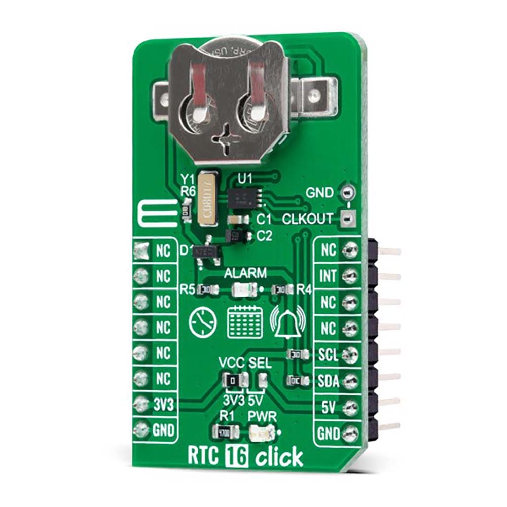
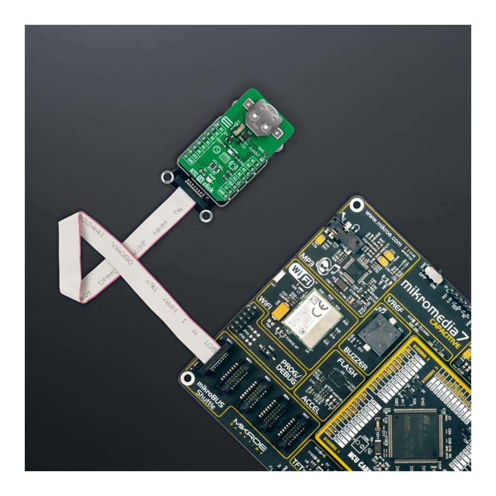
The RTC 16 Click Board™ is a compact add-on board that accurately keeps the time of a day. This board features the BU9873, a CMOS real-time clock with a built-in interrupt generation function from Rohm Semiconductors. The BU9873 provides year, month, day, weekday, hours, minutes, and seconds based on a 32.768kHz quartz crystal. This RTC is connected to the MCU through an I2C interface and configured to serial transmit time and calendar data. It also has an alarm function that outputs an interrupt signal to the MCU when the day of the week, hour, or minute matches the preset time. This Click board™ is suitable for various time-keeping applications, including daily alarms, metering applications, and others requiring an accurate RTC for their operation.
The RTC 16 Click Board™ is supported by a mikroSDK compliant library, which includes functions that simplify software development. This Click board™ comes as a fully tested product, ready to be used on a system equipped with the mikroBUS™ socket.
Downloads
How Does The RTC 16 Click Board™ Work?
The RTC 16 Click Board™ is based on the BU9873, an I2C configurable real-time clock/calendar optimized for low power operations from Rohm Semiconductors. The BU9873 is configured to perform the serial transmission of calendar and time data to the MCU and comes with an integrated interrupt generation function. It also contains a built-in high-precision oscillation adjustment circuit which enables the adjustment of time counts with a digital method and correct deviations in the oscillation frequency of the crystal oscillator. This RTC is also characterized by an automatic leap year recognition until the future 2099 year.
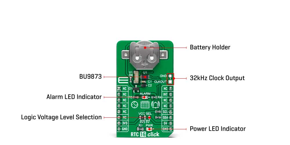
The RTC 16 Click Board™ communicates with MCU using the standard I2C 2-Wire interface to read data and configure settings, supporting a Fast Mode operation up to 400kHz. An alarm and interrupt function is also available that outputs an interrupt signal to the INT pin of the mikroBUS™ socket when the day of the week, hour, or minute matches with the preset time. An alarm may be selectable between ON and OFF for each day of the week, allowing outputting warning every day or on a specific day indicated by a red LED marked as ALARM. Besides, the RTC 16 Click also has an onboard header labelled CLKOUT, which provides clock pulses of 32kHz.
The most common RTC configuration, like this one, is a battery-backed up, which maintains time and continues its work without interruption in the event of a power failure. That's why, in addition to the BU9873, the RTC 16 Click is equipped with a button cell battery holder compatible with the 3000TR battery holder, suitable for 12mm Coin Cell batteries.
The RTC 16 Click Board™ can operate with both 3.3V and 5V logic voltage levels selected via the VCC SEL jumper. This way, it is allowed for both 3.3V and 5V capable MCUs to use the communication lines properly. However, the Click board™ comes equipped with a library that contains easy-to-use functions and an example code that can be used, as a reference, for further development.
SPECIFICATIONS
| Type | RTC |
| Applications | The RTC 16 Click Board™ can be used for various time-keeping applications, including daily alarms, metering applications, and others requiring an accurate RTC for their operation |
| On-board modules | BU9873 - CMOS real-time clock that has a built-in interrupt generation function from Rohm Semiconductors |
| Key Features | Low power consumption, clock/calendar feature, programmable periodic and alarm with interrupt capability, battery back-up, 32kHz clock output, automatic leap year recognition up to the year 2099, and more |
| Interface | I2C |
| Compatibility | mikroBUS |
| Click board size | M (42.9 x 25.4 mm) |
| Input Voltage | 3.3V or 5V |
PINOUT DIAGRAM
This table shows how the pinout of the RTC 16 Click Board™ corresponds to the pinout on the mikroBUS™ socket (the latter shown in the two middle columns).
| Notes | Pin | Pin | Notes | ||||
|---|---|---|---|---|---|---|---|
| NC | 1 | AN | PWM | 16 | NC | ||
| NC | 2 | RST | INT | 15 | INT | Interrupt | |
| NC | 3 | CS | RX | 14 | NC | ||
| NC | 4 | SCK | TX | 13 | NC | ||
| NC | 5 | MISO | SCL | 12 | SCL | I2C Clock | |
| NC | 6 | MOSI | SDA | 11 | SDA | I2C Data | |
| Power Supply | 3.3V | 7 | 3.3V | 5V | 10 | 5V | Power Supply |
| Ground | GND | 8 | GND | GND | 9 | GND | Ground |
ONBOARD SETTINGS AND INDICATORS
| Label | Name | Default | Description |
|---|---|---|---|
| LD1 | PWR | - | Power LED Indicator |
| LD2 | ALARM | - | Alarm LED Indicator |
| JP1 | VCC SEL | Left | Logic Level Voltage Selection 3V3/5V: Left position 3V3, Right position 5V |
| J1 | CLKOUT | Unpopulated | 32kHz Clock Output Header |
RTC 16 CLICK ELECTRICAL SPECIFICATIONS
| Description | Min | Typ | Max | Unit |
|---|---|---|---|---|
| Supply Voltage | 3.3 | - | 5 | V |
| Clock Output CLKOUT | - | 32 | - | kHz |
| Operating Temperature Range | -40 | +25 | +85 | °C |
| General Information | |
|---|---|
Part Number (SKU) |
MIKROE-5083
|
Manufacturer |
|
| Physical and Mechanical | |
Weight |
0.02 kg
|
| Other | |
EAN |
8606027389085
|
Frequently Asked Questions
Have a Question?
Be the first to ask a question about this.