Overview
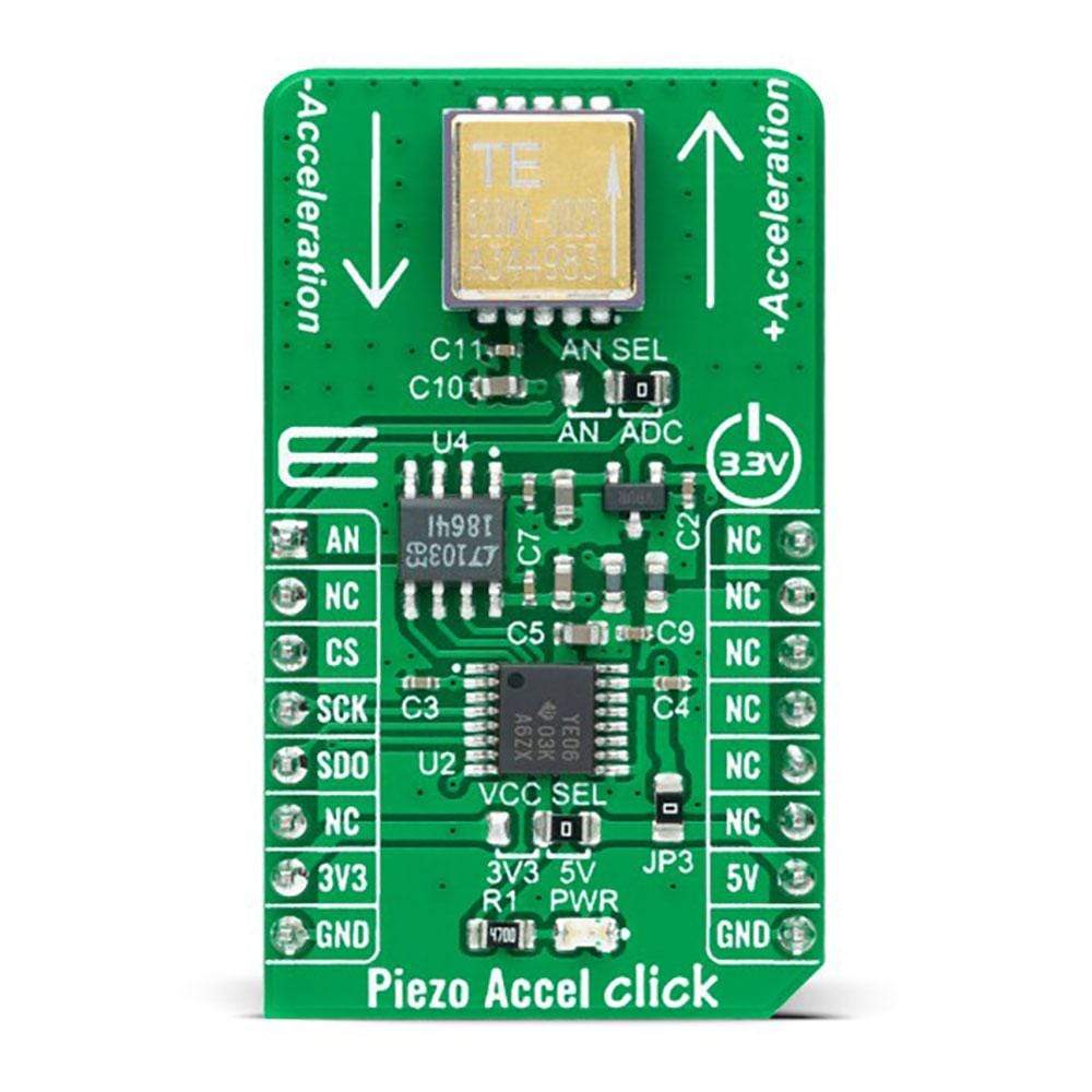
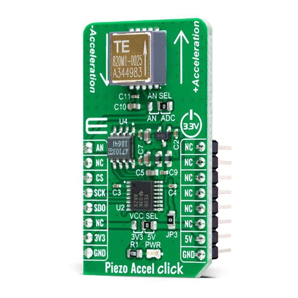
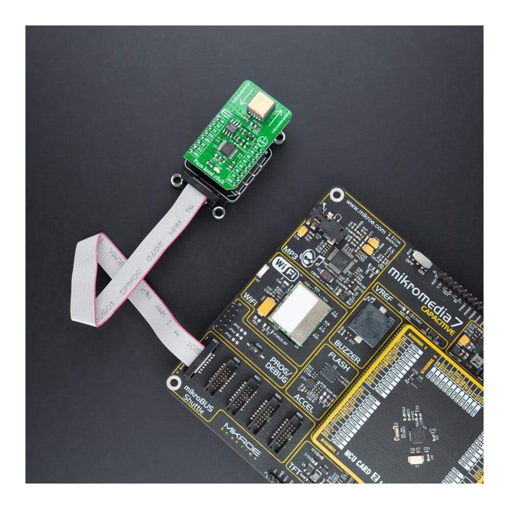
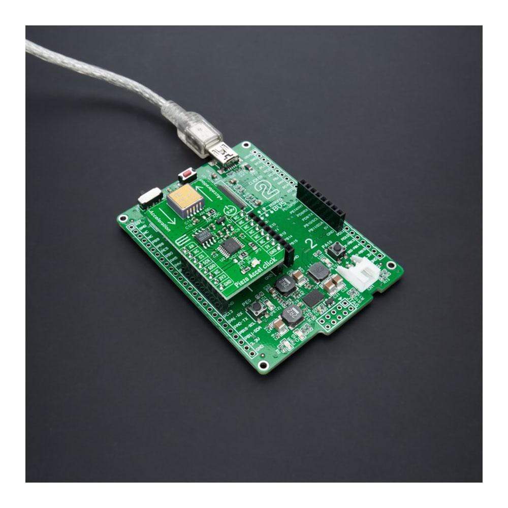
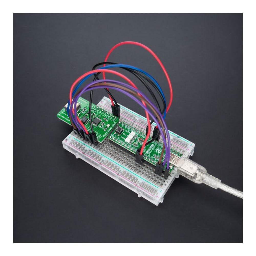
The Piezo Accel Click Board™ is a compact add-on board containing an acceleration sensor based on PE technology. This board features the 820M1-0025, a piezoelectric accelerometer designed for embedded condition monitoring and preventive maintenance applications from TE Connectivity. This accelerometer features a stable piezoceramic crystal sealed in a fully hermetic LCC package available in a range from ±25g with a flat frequency response up to 15kHz. The piezoelectric technology used by this accelerometer has a proven track record for offering the reliable and long-term stable output required for condition monitoring applications where this Click Board™ can be used.Downloads
How does the Piezzo Accel Click Board™ work?
The Piezzo Accel Click Board™, as its foundation, uses the 820M1-0025, a piezoelectric accelerometer designed for embedded condition monitoring and preventive maintenance applications from TE Connectivity. The 820M1-0025 accelerometer is available in the range of ±25g and features a flat frequency response up to >15kHz. Featuring stable piezoceramic crystals in shear mode sealed in a fully hermetic LCC package, the accelerometer incorporates an amplified ±1.25V output with optimum measurement resolution. This Click board™ is suitable for machine health monitoring and has a superior resolution, dynamic range, and bandwidth to MEMS devices.
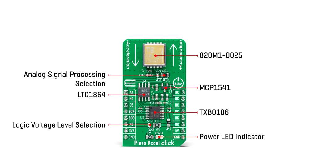
The piezoelectric technology incorporated in the 820M1-0025 accelerometer has a proven track record for offering the reliable and long-term stable output required for condition monitoring applications. This output signal can be processed in two ways, as an analogue value or converted to a digital using the LTC1864, a successive approximation A/D converter with a 16-bit resolution from Analog Devices. This ADC includes a sample-and-hold feature and has a differential analogue input with an adjustable reference pin used as the reference input resulting in accuracy and stability of the 4.096V reference voltage level provided by the MCP1541 from Microchip.
The Piezzo Accel Click Board™ communicates with MCU using the 3-Wire SPI serial interface through an earlier mentioned AD converter, the LTC1864. The 5V logic level provides a needed reference voltage for one side of the TXB0106, a 6-bit bidirectional level shifting, and a voltage translator with automatic direction sensing from Texas Instruments. On another side of the level shifter, the reference voltage is taken from the 3.3V pin from the mikroBUS™.
In addition to the AD converter, the output of the 820M1-0025 can be also sent directly to an analogue pin of the mikroBUS ™ socket labelled as AN. An output signal processing can be performed by placing an onboard SMD jumper labelled as AN SEL to an appropriate position marked as AN and ADC.
The Piezzo Accel Click Board™ can operate with both 3.3V and 5V logic voltage levels selected via the VCC SEL jumper. This way, it is allowed for both 3.3V and 5V capable MCUs to properly use the SPI communication lines. However, the Click board™ comes equipped with a library containing easy-to-use functions and an example code that can be used, as a reference, for further development.
SPECIFICATIONS
| Type | Motion |
| Applications | The Piezzo Accel Click Board™ be used for condition monitoring applications. |
| On-board modules | 820M1-0025 - piezoelectric accelerometer designed for embedded monitoring and preventive maintenance applications from TE Connectivity |
| Key Features | Piezoelectric accelerometer, wide bandwidth, a superior resolution to MEMS devices, low power consumption, and more. |
| Interface | Analog, SPI |
| Compatibility | mikroBUS |
| Click board size | M (42.9 x 25.4 mm) |
| Input Voltage | 3.3V or 5V |
PINOUT DIAGRAM
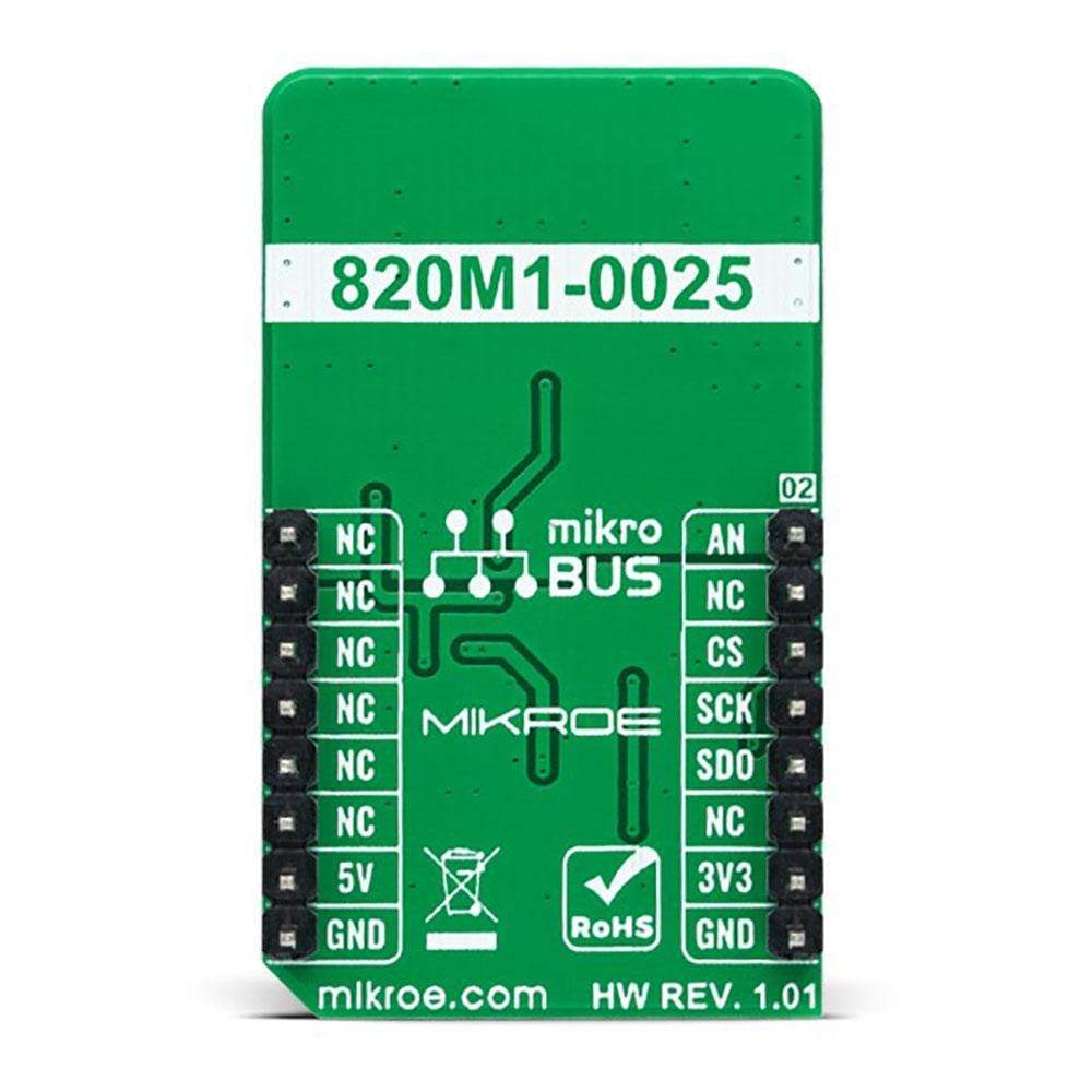
This table shows how the pinout of the Piezzo Accel Click Board™ corresponds to the pinout on the mikroBUS™ socket (the latter shown in the two middle columns).
| Notes | Pin |  |
Pin | Notes | |||
|---|---|---|---|---|---|---|---|
| Analog Signal | AN | 1 | AN | PWM | 16 | NC | |
| NC | 2 | RST | INT | 15 | NC | ||
| SPI Chip Select | CS | 3 | CS | RX | 14 | NC | |
| SPI Clock | SCK | 4 | SCK | TX | 13 | NC | |
| SPI Data OUT | SDO | 5 | MISO | SCL | 12 | NC | |
| NC | 6 | MOSI | SDA | 11 | NC | ||
| Power Supply | 3.3V | 7 | 3.3V | 5V | 10 | 5V | Power Supply |
| Ground | GND | 8 | GND | GND | 9 | GND | Ground |
ONBOARD SETTINGS AND INDICATORS
| Label | Name | Default | Description |
|---|---|---|---|
| LD1 | PWR | - | Power LED Indicator |
| JP1 | VCC SEL | Right | Logic Level Voltage Selection 3V3/5V: Left position 3V3, Right position 5V |
| JP2 | AN SEL | Right | Analog Signal Processing Selection AN/ADC: Left position AN, Right position ADC |
PIEZO ACCEL CLICK ELECTRICAL SPECIFICATIONS
| Description | Min | Typ | Max | Unit |
|---|---|---|---|---|
| Supply Voltage | 3.3 | - | 5 | V |
| Acceleration Range | - | ±25 | - | g |
| Sensitivity | - | 50 | - | mV/g |
| Bandwidth | - | - | 10 | kHz |
| Operating Temperature Range | -40 | +25 | +125 | °C |
| General Information | |
|---|---|
Part Number (SKU) |
MIKROE-4559
|
Manufacturer |
|
| Physical and Mechanical | |
Weight |
0.02 kg
|
| Other | |
Country of Origin |
|
HS Code Customs Tariff code
|
|
EAN |
8606027382178
|
Warranty |
|
Frequently Asked Questions
Have a Question?
Be the first to ask a question about this.

