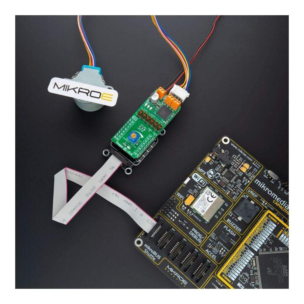
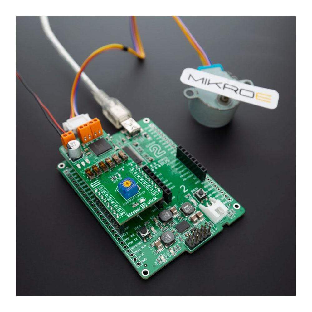
Overview
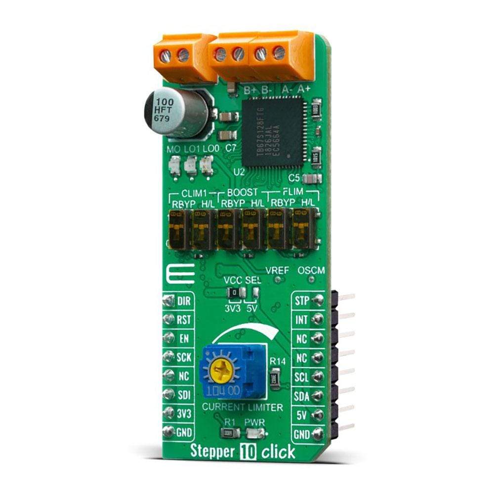
The Stepper 10 Click Board™ is a two-phase bipolar stepping motor driver capable of controlling one stepper motor with a PWM constant current drive. The Click Board™'s featured chip TB67S128FTG, from Toshiba Semiconductor, fabricated with BiCD process with an output rating of 50V/5A and a built-in decoder that can supply the motor with voltage of up to 44V. Toshiba's innovative technology process results in low-power consumption with low on-resistance (0.25Ω) on the integrated MOSFET output stage.
The stepper motor can be driven in both directions from full step to 1/128 micro-steps. The motor driver possesses features like a high-efficiency motor current control mechanism, advanced current detection system, active gain control and multi error detect functions. The Stepper 10 Click Board™ has two types of interfaces for motor control drive: CLK and Serial mode.
Downloads
The Stepper 10 Click Board™ uses the TB67S128FTG from Toshiba Semiconductor, a two-phase bipolar stepper motor driver, which features adjustable current limiting and micro-stepping down to 1/128 step operation. Fabricated using a leading-edge BiCD process with low power consumption and low output on-resistance, Toshiba's TB67S128FTG in thermally enhanced small package help improve the efficiency and reduce the size of motor applications. This stepping motor driver incorporates a high-speed, high-precision control technology required for factory automation systems and office equipment, and help reduce the number of external parts required, simplifying system design.
The chip itself can dynamically select an optimal decay mode by monitoring the actual motor current, and automatically reduce the driving current below the full amount when the motor is lightly loaded to minimize power consumption and heat generation. The driver has a wide operating voltage range of 6.5 V to 44 V and can deliver approximately 2.1 A per phase continuously without a heat sink or forced air flow (up to 5 A peak). It features built-in protection against under-voltage, over-current, and over-temperature conditions. Before using this product, it is strongly recommended that the TB67S128FTG datasheet is read carefully.
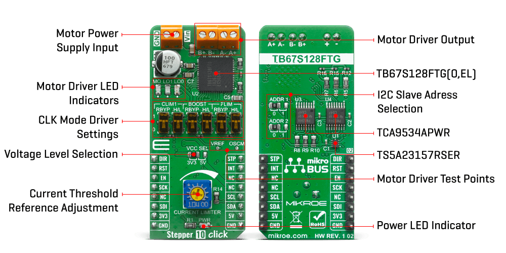
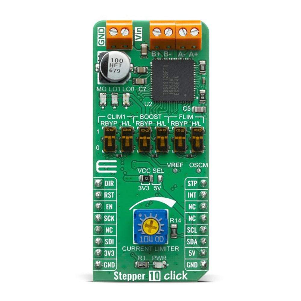
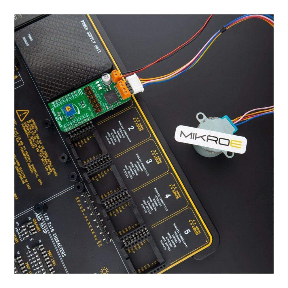
First off, the TB67S128FTG motor driver requires a supply voltage of 6.5 V to 44 V to be connected across VIN and GND. This supply should be capable of delivering the expected stepper motor current. The motor driver provides a 5V output from the internal regulator supplying the neighbouring external loads like pins OSCM, VREF, CLIM1, BST, FLIM, GAIN_SEL and monitoring LEDs MO, LO1 and LO0. Right next to the motor power supply connector, two output channels (A and B) are located for the stepper motor connection. It is not advised to connect or disconnecting a stepper motor while the driver is powered since it can result in chip failure.
There are two interface modes to select from:
- CLK mode for simple step and direction control
- Serial mode for controlling and setting the driver through a serial interface
Step resolution is configurable using MODE2, MODE1 and MODE0, by setting the appropriate pin level. Most of the pins are controlled using an IO expander via the I2C bus except DIR, STEP, ENABLE and RESET which are routed to Mikrobus. Stepper 10 click has eight different step modes: full-step, half-step, 1/4-step, 1/8, 1/16, 1/32, 1/64, and 1/128. Besides that, four different decay modes are available using the MDT0 and MDT1 pins. The onboard trimmer potentiometer can be used to set the current limit to prevent damage to the motor. The actual calculation of the predefined output current can be found in the TB67S128FTG datasheet.
Toshiba's unique AGC feature stepping motor technology automatically optimizes the drive current in real-time according to the load torque. It helps reduce unnecessary current, drastically cut power consumption and heat generation. AGC is configured with six pins (AGC, CLIM0, CLIM1, FLIM, BOOST, and LTH). CLIM1, FLIM, and BOOST (BST) are four-state logic inputs that can be tied high to VCC, pulled high through a 100kΩ resistor, pulled low through a 100kΩ resistor, or tied low to GND. This is done by using the onboard switches, one for logic level and one to bypass the 100kΩ resistor by choice.
Stepper 10 Click has the function to detect several error states indicated by two LEDs: LO1 and LO0. If the overcurrent is detected, the LO0 will toggle, while the LO1 represents the motor load open indication. If both LEDs are toggled, then the thermal shutdown is detected. The errors are cleared by toggling standby mode or by performing a power cycle to the driver. The LED designated as MO is toggled if the driver's electrical angle is equal to the initial value of 45°, which occurs immediately after reset or whenever the driver has stepped a full cycle.
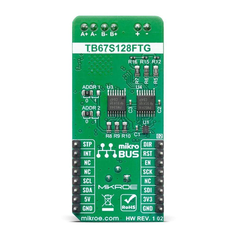
The Stepper 10 Click Board™ uses the two TCA9534APWR Low-Power IO Expanders that support the I2C interface protocol. In order to avoid conflicts on the bus, the slave addresses can be reconfigured by an SMD jumper labelled as ADDR1 and ADDR2.
The Stepper 10 Click Board™ can be supplied and interfaced with both 3.3V and 5V without the need for any external components. The onboard SMD jumper labelled as VCC SEL allows voltage selection for interfacing with both 3.3V and 5V microcontrollers.
Specifications
| Type | Stepper |
| Applications | The Stepper 10 Click Board™ is a perfect solution for building various applications that require advanced stepper motor control, with maximum precision and reliability. |
| On-board modules | The Stepper 10 Click Board™ uses the TB67S128FTG IC, a two-phase bipolar stepper motor driver using a PWM chopper, from Toshiba Semiconductor |
| Key Features | Allows full, half, quarter, 1/8, 1/16, 1/32, 1/64, 1/128 step operation, low on-resistance. MOSFET output stage, high-efficiency motor current control mechanism, built-in anti-stall architecture, built-in sense resistor less current control architecture, high voltage and current, multi error detect functions |
| Interface | GPIO,I2C,SPI |
| Compatibility | mikroBUS |
| Click board size | L (57.15 x 25.4 mm) |
| Input Voltage | 3.3V,5V |
Pinout Diagram
This table shows how the pinout on Stepper 10 Click Board™ corresponds to the pinout on the mikroBUS™ socket (the latter shown in the two middle columns).
| Notes | Pin |  |
Pin | Notes | |||
|---|---|---|---|---|---|---|---|
| Current direction | DIR | 1 | AN | PWM | 16 | STEP | Step clock input |
| Reset | RST | 2 | RST | INT | 15 | INT | Interrupt |
| Motor outout enable | EN | 3 | CS | RX | 14 | NC | |
| SPI Clock | SCK | 4 | SCK | TX | 13 | NC | |
| NC | 5 | MISO | SCL | 12 | SCL | I2C Clock | |
| SPI Data IN | SDI | 6 | MOSI | SDA | 11 | SDA | I2C Data |
| Power Supply | 3.3V | 7 | 3.3V | 5V | 10 | 5V | Power supply |
| Ground | GND | 8 | GND | GND | 9 | GND | Ground |
Onboard Settings and Indicators
| Label | Name | Default | Description |
|---|---|---|---|
| LD1 | PWR | - | Power LED Indicator |
| LD2 | MO | - | Electrical angle LED Indicator |
| LD3 | LO1 | - | Error detection LED Indicator 1 |
| LD4 | LO0 | - | Error detection LED Indicator 0 |
| JP1, JP2 | ADDR SEL | Left | Communication Interface Selection: left position 0, right position 1 |
| JP3 | VCC SEL | Left | Power Supply Voltage Selection: left position 3V3, right position 5V |
| VR1 | Current Limiter | - | Current Threshold Reference Adjustment |
| SW1-SW3 | R_BYPASS | Up | Switch bypassing 100kΩ resistor: Up - short, Down - open |
| SW4 | CLIM1 | Up | Bottom Current Limit CLIM1 Logic Level Selection: Up - VCC, Down - GND |
| SW5 | BOOST | Up | Current BOOST Logic Level Selection: Up - VCC, Down - GND |
| SW6 | FLIM | Up | Frequency Limit FLIM Logic Level Selection: Up - VCC, Down - GND |
Stepper 10 Click Electrical Specifications
| Description | Min | Typ | Max | Unit |
|---|---|---|---|---|
| Supply Voltage | -0.4 | 3.3 | 6 | V |
| Motor Supply Voltage | -0.4 | - | 44 | V |
| Motor Output Current | - | - | 5¹ | A |
| Operating Temperature Range | -45 | - | 80 | °C |
Note 1: Usually, the maximum current value at the time should use 70% or less of the absolute maximum ratings for a standard on thermal rating. The maximum output current may be further limited given thermal considerations, depending on ambient temperature and board conditions.
| General Information | |
|---|---|
Part Number (SKU) |
MIKROE-4138
|
Manufacturer |
|
| Physical and Mechanical | |
Weight |
0.023 kg
|
| Other | |
Country of Origin |
|
HS Code Customs Tariff code
|
|
EAN |
8606018717804
|
Warranty |
|
Frequently Asked Questions
Have a Question?
Be the first to ask a question about this.


