


Mikroelektronika d.o.o.
ECG 6 Click Board™
ECG 6 Click Board™
SKU: MIKROE-4061
Couldn't load pickup availability


Overview
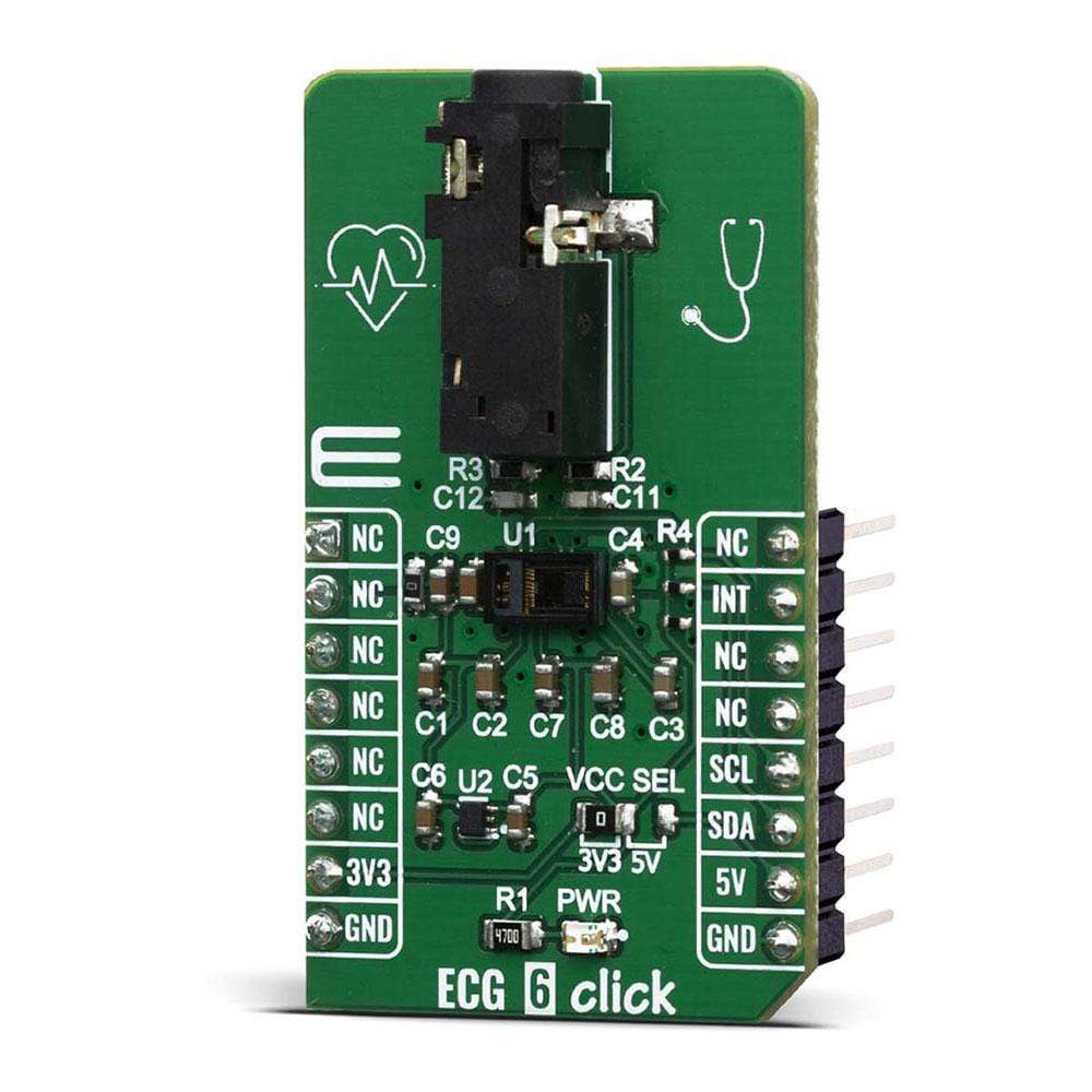
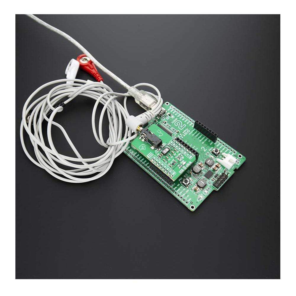
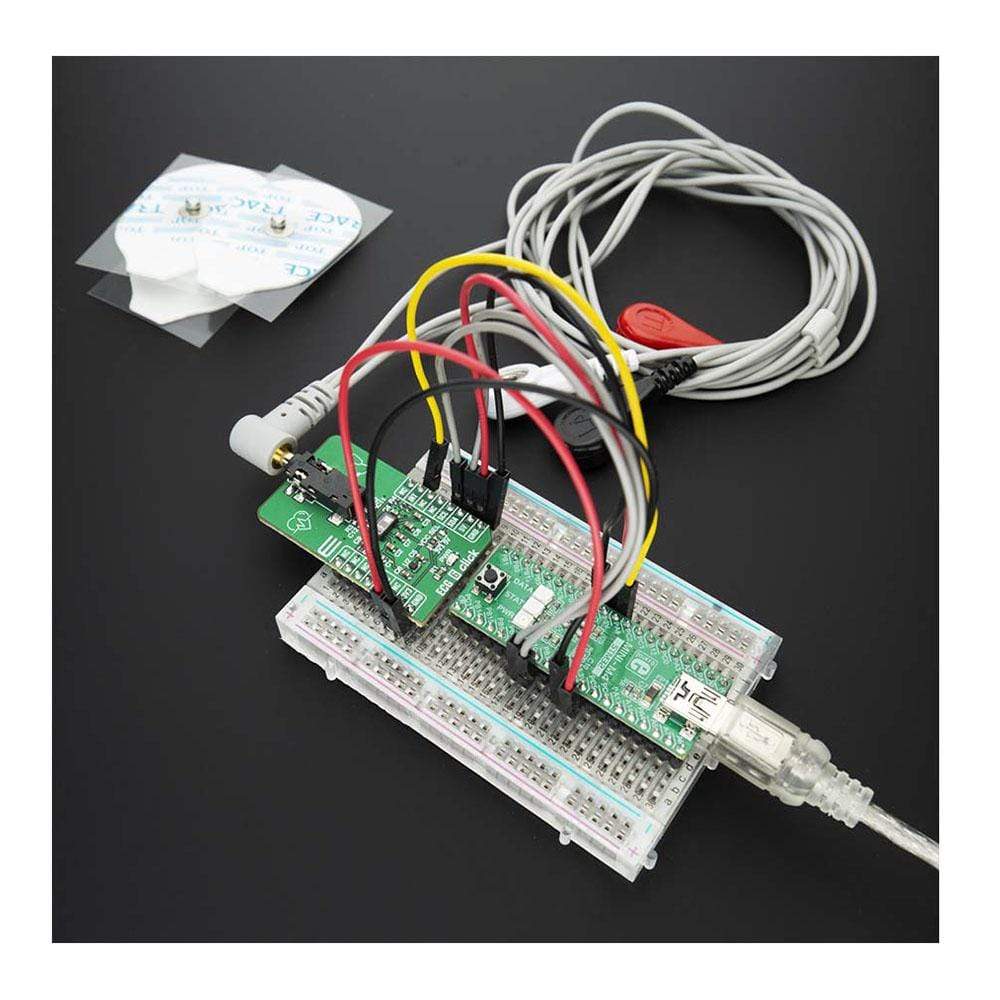
The ECG 6 Click Board™ is a complete solution for the development of ECG and Heart-Rate (HR) applications. It features the MAX86150, a Reflective Heart Rate Monitor and Medical-Grade Pulse Oximeter from Maxim Integrated. The Click Board™ contains an integrated electrocardiogram, pulse oximeter, heart rate monitor sensor module. The ECG 6 Click can be used for application in Fitness Assistant Devices, Wearable Devices, Smartphones, Tablet.
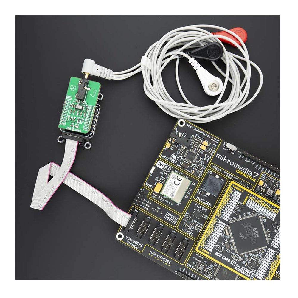
The ECG 6 click is supported by a mikroSDK compliant library, which includes functions that simplify software development. This Click Board™ comes as a fully tested product, ready to be used on a system equipped with the mikroBUS™ socket.
Note: ECG 6 is a development and prototyping tool. It is not intended to be used for the medical treatment of patients, and should not be used to diagnose or treat any conditions.
Downloads
How Does The ECG 6 Click Board™ Work?
The ECG 6 Click Board™ is based on the MAX86150, is a complete electrocardiogram (ECG) from Maxim Integrated. It is designed for mobile health. The Click board™ has many features to provide health measurements: electrocardiogram, pulse oximetry, and heart rate. All these features allow ECG 6 click to be used in a range of health-related ECG, SpO2 subsystem and HR applications including fitness and activity heart rate monitors, portable ECG, wearable and remote health monitors, and similar.
The MAX86150 contain integrated the SpO2 subsystem. The SpO2 subsystem is peripheral capillary oxygen saturation. It is measured by a device called a pulse oximeter. A clip is placed on the finger or foot of the patient and light is sent through the finger and measured on the other side. The MAX86150 integrates red and infrared LED drivers to modulate LED pulses for SpO2 and HR measurements. The LED current can be programmed from 0mA to 100mA with proper VLED supply voltage. The LED pulse width can be programmed from 50μs to 400μs to optimize accuracy of results and power consumption based on use cases.
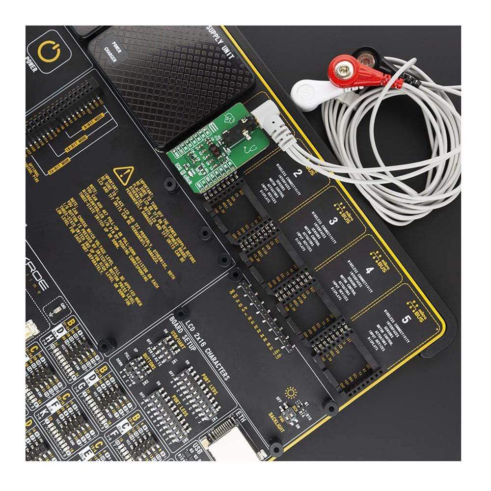
The ECG 6 Click Board™ allows several types of electrodes to be used. It supports both stainless-steel and silver-chloride electrode types. The electrodes are used to perform differential measurement of the voltage generated by the heart. Therefore, the heart can be monitored from a single plane only - the coronal plane. However, this is quite enough for the fitness, heart rate monitoring and similar applications.
The extensive interrupt engine can be used to trigger the host MCU from various sources, including interrupt events due to lead detection, R-R detection, fast-recovery event, FIFO buffer states, and many more. These interrupt sources can be utilized to trigger a state change on the interrupt pin (INT) of the MAX86150 IC. This pin is active-low.
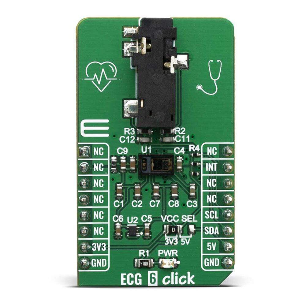
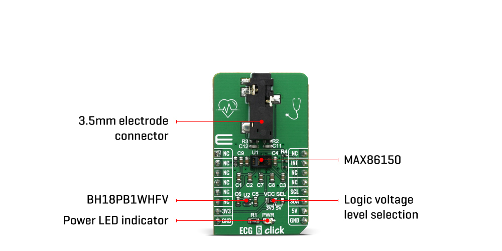
The voltage level of the logic section can be selected via VCC SEL jumper, between 3.3V and 5V. This allows for both 3.3V and 5V capable MCUs to use the SPI communication lines properly.
SPECIFICATIONS
| Type | Biometrics,ECG |
| Applications | Medical health: Fitness Assistant Devices, Wearable Devices, Smartphones, Tablet, |
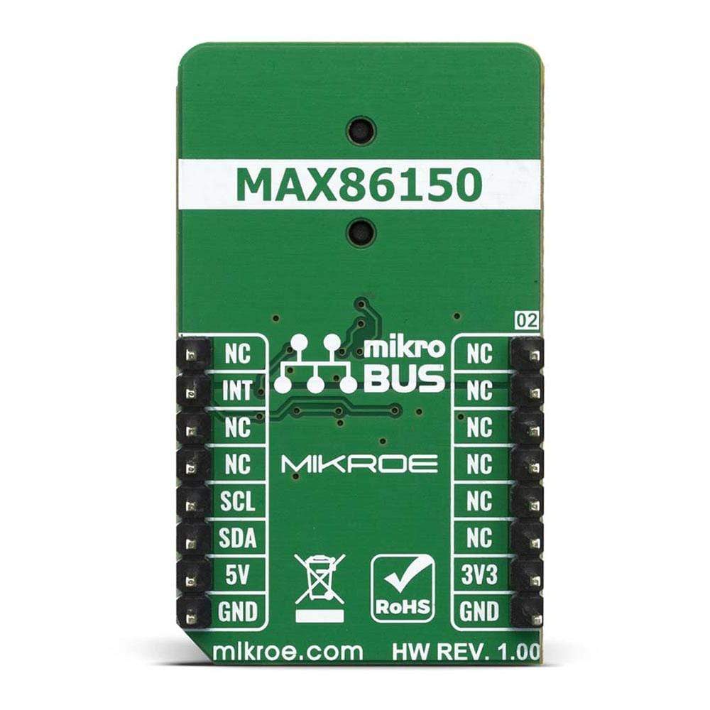
| On-board modules | MAX86150 electrocardiogram from Maxim Integrated. |
| Key Features | Reflective Heart Rate Monitor, Medical-Grade Pulse Oximeter, |
| Interface | I2C |
| Compatibility | mikroBUS |
| Click board size | M (42.9 x 25.4 mm) |
| Input Voltage | 3.3V or 5V |
PINOUT DIAGRAM
This table shows how the pinout on the ECG 6 Click Board™ corresponds to the pinout on the mikroBUS™ socket (the latter shown in the two middle columns).
| Notes | Pin | Pin | Notes | ||||
|---|---|---|---|---|---|---|---|
| NC | 1 | AN | PWM | 16 | NC | ||
| NC | 2 | RST | INT | 15 | INT | Interrupt OUT | |
| NC | 3 | CS | RX | 14 | NC | ||
| NC | 4 | SCK | TX | 13 | NC | ||
| NC | 5 | MISO | SCL | 12 | SCL | I2C Clock | |
| NC | 6 | MOSI | SDA | 11 | SDA | I2C Data | |
| Power Supply | 3.3V | 7 | 3.3V | 5V | 10 | 5V | Power supply |
| Ground | GND | 8 | GND | GND | 9 | GND | Ground |
ONBOARD SETTINGS AND INDICATORS
| Label | Name | Default | Description |
|---|---|---|---|
| JP1 | VCC SEL | Left | Power supply voltage selection: left position 3.3V, right position 5V |
| LD1 | PWR | - | Power LED indicator |
| CN1 | 3.5mm JACK | - | 3.5mm electrodes connector |
| General Information | |
|---|---|
Part Number (SKU) |
MIKROE-4061
|
Manufacturer |
|
| Physical and Mechanical | |
Weight |
0.02 kg
|
| Other | |
EAN |
8606018717187
|
Frequently Asked Questions
Have a Question?
Be the first to ask a question about this.