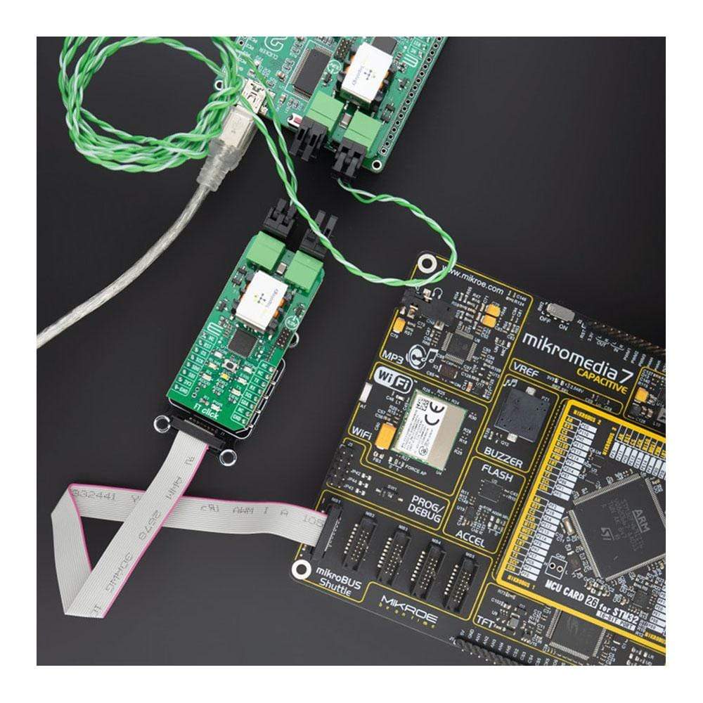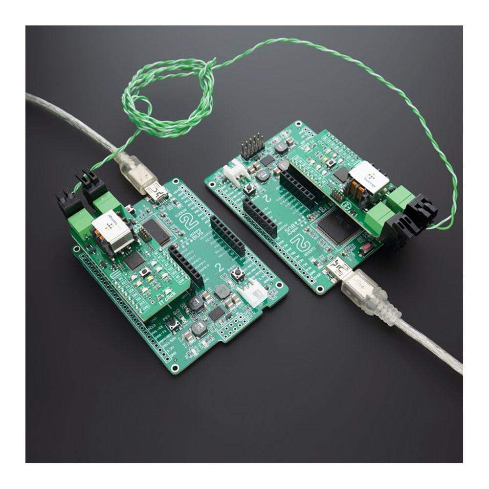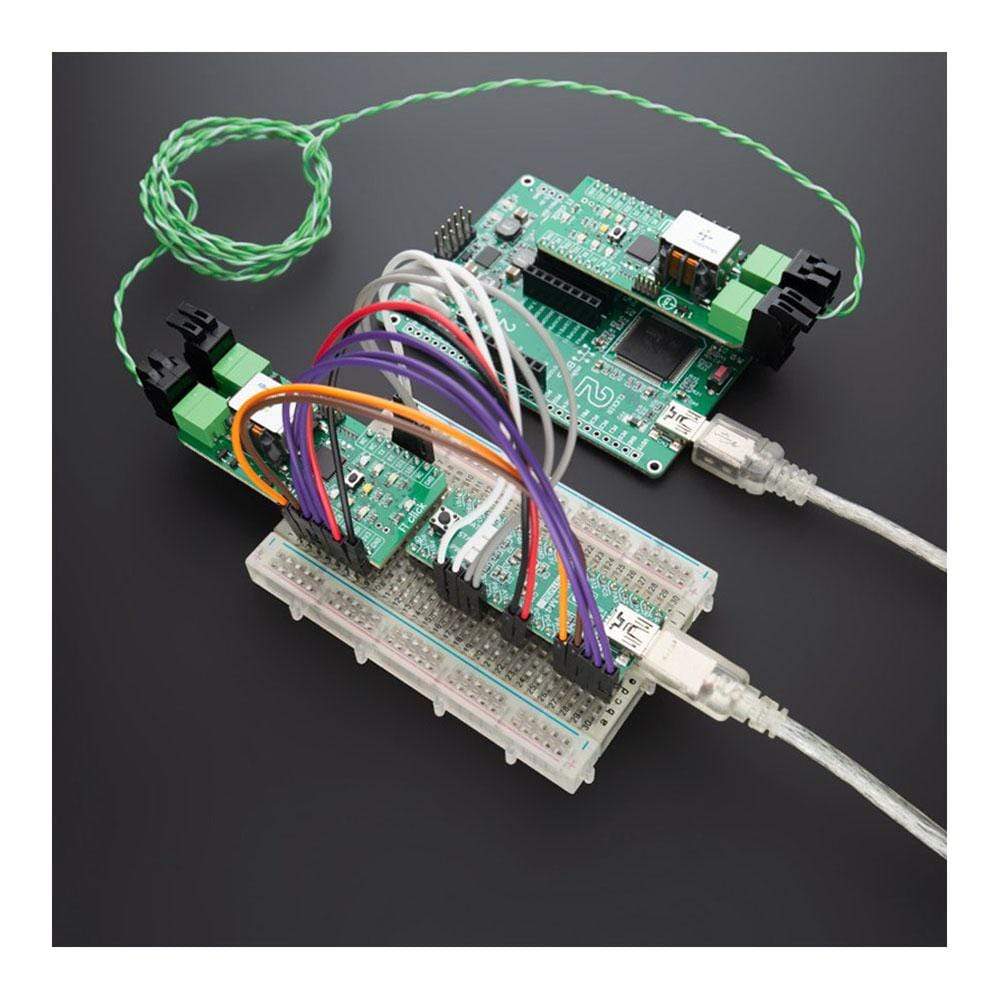
Overview
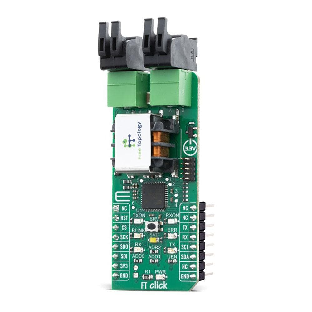
The FT Click Board™ is a compact smart transceiver add-on board that helps you add a Free Topology (FT) interface to any host board with the mikroBUS™ socket. Leveraging FT, the most reliable and easiest-to-scale wired communications media, FT Click Board™ lets you network sensors and devices to create IoT solutions for automation and control networks that are easier to develop, integrate and install. This Click Board™ supports full communication stacks for LON® and BACnet FT, as well as FTMQ (MQTT like messaging format) on board to simplify integration of BACnet, LON or custom IoT networks over twisted pair wire.
The FT Click Board™ is ideal for markets including smart buildings, cities, machines, agriculture, manufacturing, transportation and many more where wireless communications do not provide the required reliability and scale.
Downloads
How Does The FT Click Board™ Work?
The FT Click Board™ is based on the FT 6050 by Dialog Semiconductor. The transceiver is designed to simplify integration and maintenance of a complete system, and supports polarity-insensitive cabling using star, bus, daisy chain, loop, or combined topologies. The flexibility of Free Topology wiring frees the installer from the need to adhere to a strict set of wiring rules, reducing the time and expenses of device installation. It also simplifies network expansion by eliminating restrictions on wire routing, splicing, and device placement.
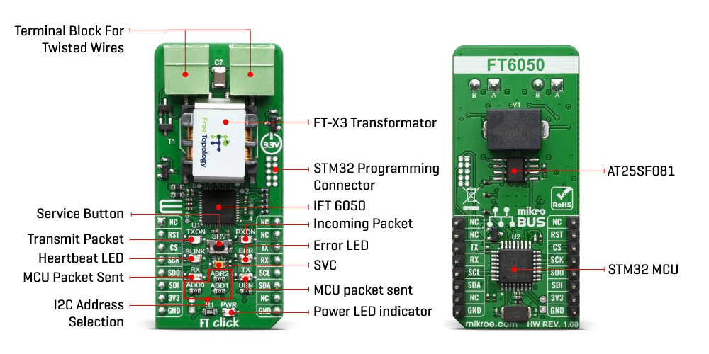
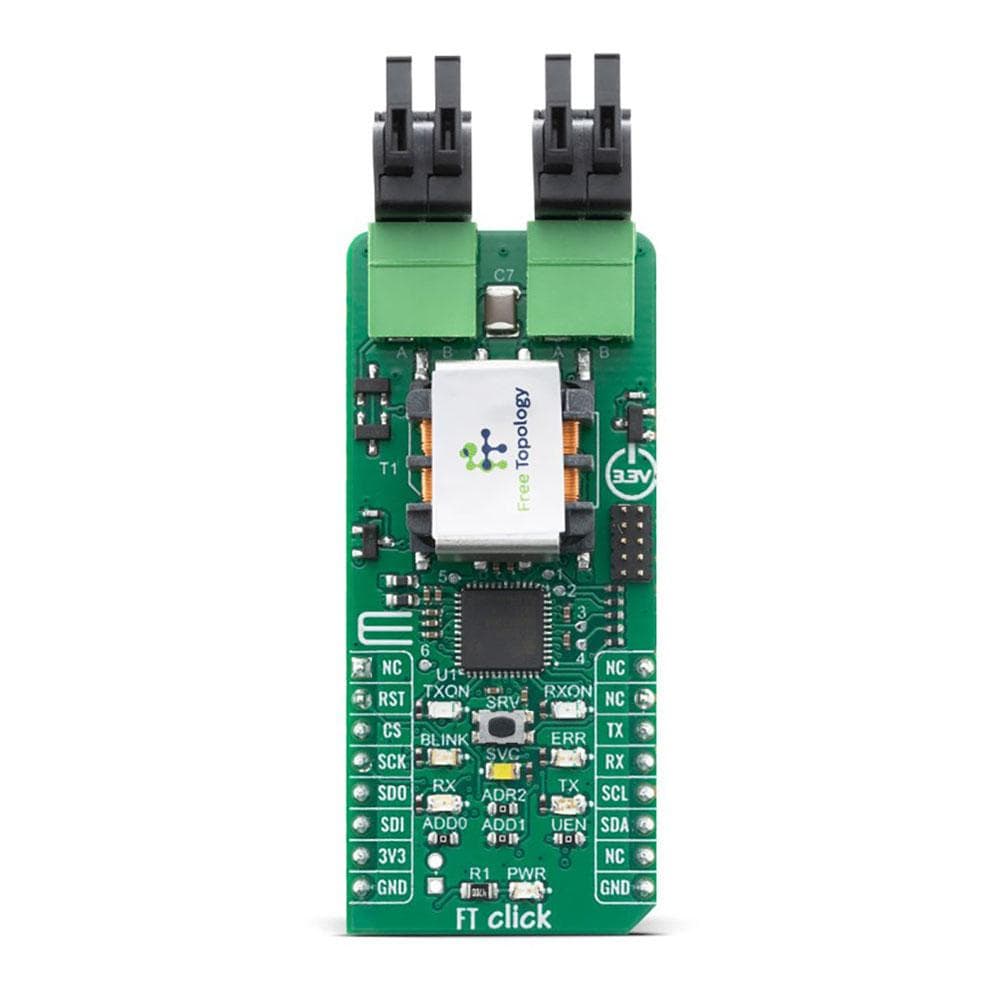
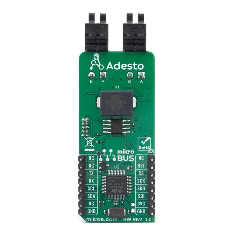
The FT Click Board™ works as the communication layer for any embedded application. The main component is the system-on-chip FT 6050 smart transceiver, which combines strengths of BACnet and LON for the first time in one solution. In addition to the transceiver, on this board we have several other building blocks from Dialog including the FT-X3 communications transformer which provides reliable communication without interference, and external AT25SF081 flash memory for storing additional resources for the FT 6050. In addition, the board also features an STMicroelectronics microcontroller whose role is to hold network custom stacks and APIs that are interpreted through the FT transceiver.
The FT 6050 chip includes multiple processors, read-write and read-only memory (RAM and ROM), communication subsystems, and I/O subsystems. Each FT 6050 chip includes a processor core for running applications and managing network communications, memory, I/O, and a 48-bit identification number (the Neuron ID) that is unique to every device. FT 6050 devices simultaneously provide a LON, LON/IP, BACnet/IP Server, BACnet MS/TP server, and messaging interface.
As mentioned, the FT Click uses an external AT25SF081 flash of 8Mb for storing additional resources for the FT 6050. This flash contains active and standby bootloaders, system images, and applications. It also holds persistent system and application data, as well as data logs. Larger applications can be supported because certain code can be designated to be "transient" which means it is brought into RAM for execution out of flash only on demand.
The FT-X3 external communication transformer enables operation in the presence of high frequency common-mode noise on unshielded twisted-pair networks. The transformer also offers outstanding immunity from magnetic noise, eliminating the need for protective magnetic shields in most applications ensuring robust communication.
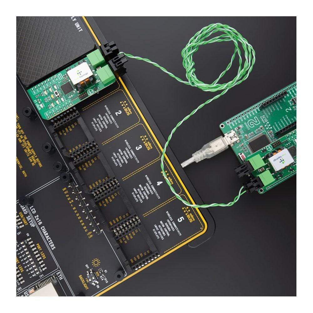
The FT Click interface supports all two-wire "Free Topology" twisted-pair networks with polarity-insensitive star, daisy chain, bus, loop, trunked, or mixed topology wiring with very high noise immunity.
Summary of Benefits of FT Click:
- Simple messaging (FTMQ) to full IP based network communications stacks (BACnet and LON) on same board
- Easy to install, fault tolerant, error free communication media using Dialog's Free Topology technology and FT 6050 Smart Transciever
- Highly reliable and scalable communication alternative to wireless protocols
- Lowest cost of ownership and installation compatred to wired protocols such as RS485 and Ethernet
- Works with any mikroBUS compatible development boards, sensors and devices
Software Stack
There are 3 basic sets of APIs included in the FT click software libraries: "FTMQ", BACnet and LON. These source code libraries support multiple development platforms such as ST M32 Nucleo, Arduino and Raspberry Pi.
The simplest "MQTT-like" protocol called FTMQ provides a familiar interface for subscribing to, and publishing, messages on topics, without requiring a broker (but otherwise very similar to MQTT). The intent of this protocol is to enable a quick-as-possible and familiar startup without need for further setup such as device ID or station address. Also provided is a FTMQ-to-MQTT bridge that runs on a R-Pi or other Linux platform to upconvert this protocol to fully compliant MQTT messaging.
For users considering using the FT6050 chip in embedded OEM designs utilizing BACnet and LON protocols, there are multiple options.
BACnet stack using FT as the data link (BACnet FT) supports BACnet configurations such as Routing, Alarming, COVs, Segmentation, BACnet/IP, BACnet/SC, and BACnet MS/TP is available from ConnectEx, Inc.
BACnet stack using FT as the data link (BACnet FT) supports BACnet configurations such as Routing, Alarming, COVs, Segmentation, BACnet/IP, BACnet/SC, and BACnet MS/TP is available from ConnectEx, Inc.
For either LON or BACnet support, please contact:
- edge.info@diasemi.com (LON development)
- info@connect-ex.com (BACnet development)
SPECIFICATIONS
| Type | Free Topology |
| Applications | The FT Click Board™ for markets including smart buildings, cities, machines, agriculture, manufacturing, transportation and many more where wireless communications do not provide the required reliability and scale. |
| On-board modules | FT 6050 Free Topology Smart Transceiver integrates a high-performance Neuron core with a Free Topology twisted pair transceiver, FT-X3 is external communication transformer that enables operation in the presence of high frequency common-mode noise |
| Key Features | Multi drop free topology fieldbus supporting 64 devices per channel; Polarity insensitive, isolated, and highly fault or noise tolerant; 78 kbps up to 500m (using free topology) and 2700m (using terminated bus); Unique IDs and automatic addressing scheme available; Supports link power; Uses inexpensive twisted pair wiring |
| Interface | I2C,SPI,UART |
| Compatibility | mikroBUS |
| Click board size | L (57.15 x 25.4 mm) |
| Input Voltage | 3.3V |
PINOUT DIAGRAM
This table shows how the pinout of the FT Click Board™ corresponds to the pinout on the mikroBUS™ socket (the latter shown in the two middle columns).
| Notes | Pin |  |
Pin | Notes | |||
|---|---|---|---|---|---|---|---|
| NC | 1 | AN | PWM | 16 | NC | ||
| Reset | RST | 2 | RST | INT | 15 | NC | |
| SPI Chip Select | CS | 3 | CS | RX | 14 | TX | UART Transmit |
| SPI Clock | SCK | 4 | SCK | TX | 13 | RX | UART Receive |
| SPI Data OUT | SDO | 5 | MISO | SCL | 12 | SCL | I2C Clock |
| SPI Data IN | SDI | 6 | MOSI | SDA | 11 | SDA | I2C Data |
| Power Supply | 3.3V | 7 | 3.3V | 5V | 10 | NC | |
| Ground | GND | 8 | GND | GND | 9 | GND | Ground |
ONBOARD SETTINGS AND INDICATORS
| Label | Name | Default | Description |
|---|---|---|---|
| T2 | SRV | - | Allows individual devices to be identified, and/or bound, on a network of perhaps hundreds or thousands of devices |
| LD1 | PWR | - | Power LED Indicator |
| LD2 | TX | - | FT Click to Host Microcontroller packet sent |
| LD3 | RX | - | Host Microcontroller to FT Click packet received |
| LD4 | ERR | - | Error LED indicating possible errors, system, network or other(under user control) |
| LD5 | BLINK | - | Heartbeat LED showing operational status of the module (under user control) |
| LD6 | SVC | - | Flashes in accordance to the FT6050 documentation to indicate the state of the FT6050 chip on the network. Normally OFF and will only be used in advanced use-case scenarios. Also used to identify a given FT6050 device on the network by using the "Wink" command, either from the FT network side using LON tools, or via the host application layer. |
| LD7 | TXON | - | Transmit packet on FT Network sent |
| LD8 | RXON | - | Incoming packet from FT Network received |
| R7 | UEN | Populated | UART enable |
| R8,R9,R10 | - | Populated | I2C Address |
| General Information | |
|---|---|
Part Number (SKU) |
MIKROE-3929
|
Manufacturer |
|
| Physical and Mechanical | |
Weight |
0.032 kg
|
| Other | |
Country of Origin |
|
HS Code Customs Tariff code
|
|
EAN |
8606018718979
|
Warranty |
|
Frequently Asked Questions
Have a Question?
Be the first to ask a question about this.

