Overview
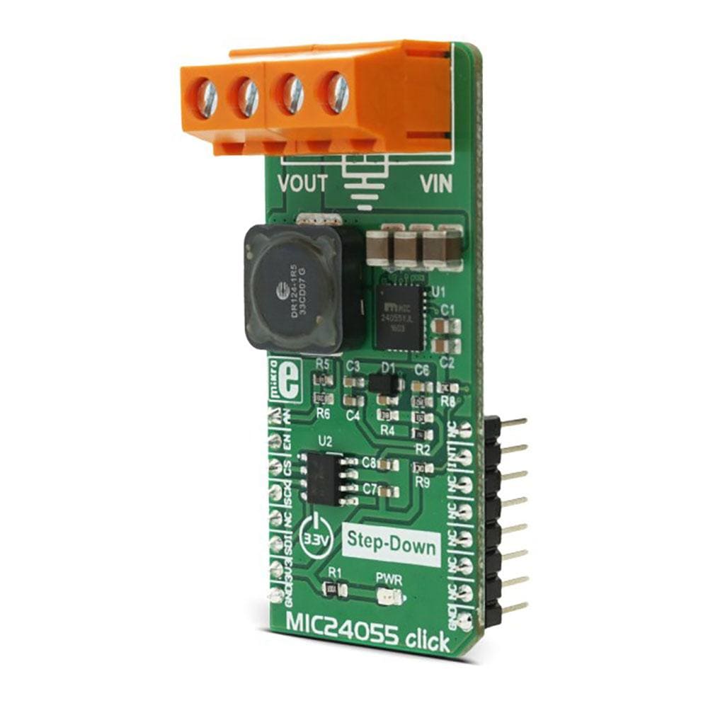
The MIC24055 Click Board™ is the buck regulator that can deliver continuous output current up to 8A and can step down voltages from up to 19V which makes this Click Board™ easy to use with many power sources commonly available. The amount of current it can deliver and the steady, ripple-free regulated voltage, make the MIC24055 Click Board™ a perfect choice for powering up devices which require high current, regulated power supply, such as servers and workstations, routers, telecom equipment and every other electronic device with similar power demands.
Downloads
The MIC24055 Click Board™ is the buck regulator that can deliver continuous output current up to 8A and can step down voltages from up to 19V which makes this click board easy to use with many power sources commonly available. The amount of current it can deliver and the steady, ripple-free regulated voltage, make this click board a perfect choice for powering up devices which require high current, regulated power supply, such as servers and workstations, routers, telecom equipment and every other electronic device with similar power demands.
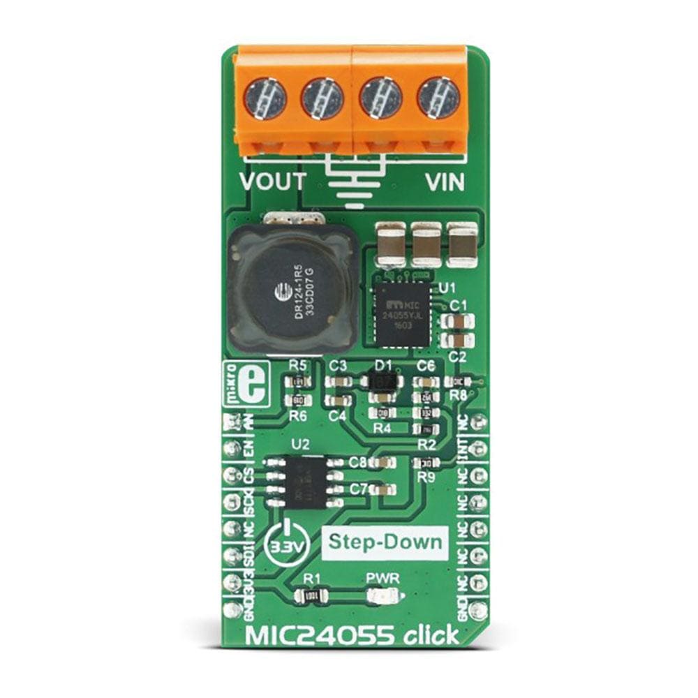
The MIC24055 Click Board™ is equipped with the MIC24055, high-efficiency buck regulator from Microchip. This IC can work with the wide range of input voltages, from 4.5V up to 19V. The regulated voltage at the output can be set from 1V to 4.8V by the means of the feedback (FB) pin and the second chip on board - MCP4921, a single channel 12-bit DAC by Microchip, equipped with the SPI interface. By programming the output of this DAC through the SPI interface routed to the mikroBUS socket pins, it is possible to easily set up the output voltage of the buck regulator. MikroElektronika libraries make it possible to perform this task easily, as seen in the example application.
How Does The MIC24055 Click Board™ Work?
The MIC24055 IC is used on this click board as the main buck regulating element. It is a synchronous buck regulator from Microchip, which works with the fixed switching frequency of 600kHz, featuring a unique adaptive on-time control architecture. This buck regulator accepts input voltages from 4.5V to 19V and outputs voltage from 1V to 4.8V. The buck regulator IC provides a full suite of safekeeping features to ensure the protection of the IC during fault conditions, such as the under-voltage lockout, internal soft-start to reduce inrush current, short-circuit protection and thermal shutdown. MIC24055 click is capable of delivering up to 8A of continuous output current on its output connector.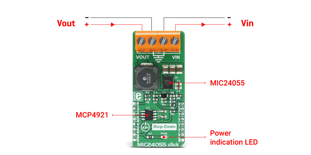
To set the desired output voltage, the MIC24055 relies on the feedback voltage of the FB pin. For that purpose, the FB pin of the MIC24055 is connected to the MCP4921 DAC converter VOUT pin. The MCP4921 DAC uses the SPI interface and it can be programmed to output a specific voltage level to the FB pin of the buck regulator. That way, the output voltage of the buck regulator can be adjusted to the desired level. The buck regulator output voltage is also fed back to the AN pin of the click board, through the voltage divider. This allows for checking the output voltage of the regulator, so the software can additionally adjust the level of the DAC output if needed. For the proper operation of the device, the input voltage needs to be greater than the set output voltage.
Besides the AN pin, the click board uses the SPI interface pins, EN pin - which is used to enable the buck regulator chip and the INT pin, which is routed to the PG pin of the MIC24055 buck regulator. This pin is an open drain output pin, used to signalize the Power Good condition, which occurs when the output voltage level (VOUT) reaches 92% of its steady-state voltage level. This pin is supplied with the pull-up resistor, connected to the 3.3V rail.
The MIC24055 Click Board™ is also equipped with the two 18A connectors, for an easy and secure connection of the input and output lines.
SPECIFICATIONS
| Type | Buck |
| Applications | The MIC24055 Click Board™ can be used for powering up devices which require regulated power source with sufficient current, such as servers and work stations, routers, telecom equipment and every other electronic device with similar power demands. |
| On-board modules | Microchip's MIC24055 constant-frequency synchronous buck regulator. Microchip's MCP4921 single channel, 12-bit DAC with the SPI interface. |
| Key Features | Continuous output current up to 8A, wide input range from 4.5V to 19V, power good (PG) output, short circuit protection, under-voltage protection, fast transient response. |
| Interface | Analog,GPIO,SPI |
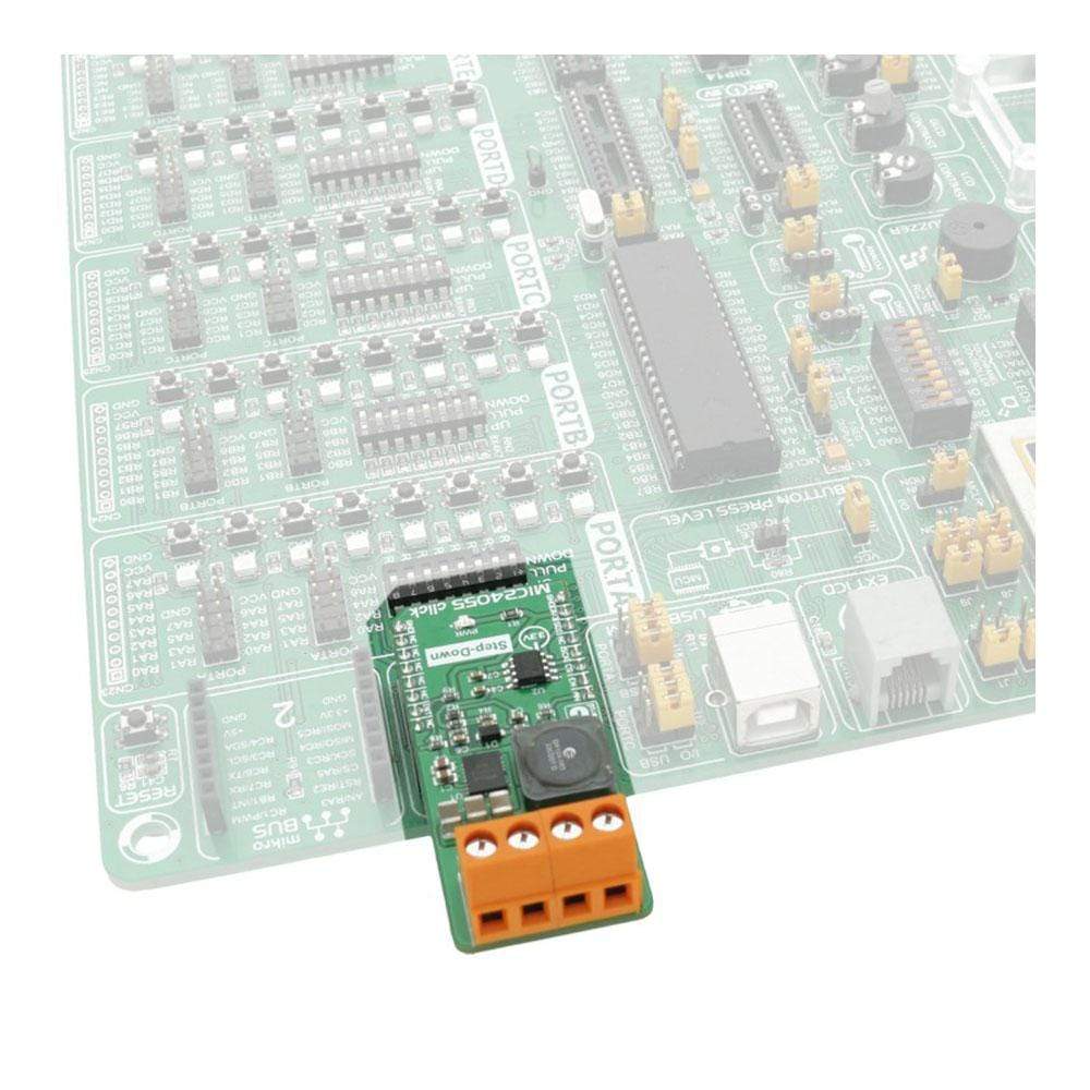
| Compatibility | mikroBUS |
| Click board size | L (57.15 x 25.4 mm) |
| Input Voltage | 3.3V |
PINOUT DIAGRAM
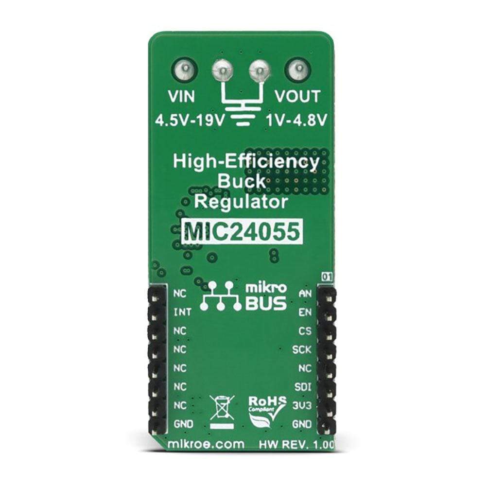
This table shows how the pinout of the MIC24055 Click Board™ corresponds to the pinout on the mikroBUS™ socket (the latter shown in the two middle columns).
| Notes | Pin |  |
Pin | Notes | |||
|---|---|---|---|---|---|---|---|
| Analog In | AN | 1 | AN | PWM | 16 | NC | |
| MIC24055 Enable | EN | 2 | RST | INT | 15 | INT | Power Good Out |
| DAC Chip Select | CS | 3 | CS | RX | 14 | NC | |
| SPI Clock | SCK | 4 | SCK | TX | 13 | NC | |
| NC | 5 | MISO | SCL | 12 | NC | ||
| SPI SDI | MOSI | 6 | MOSI | SDA | 11 | NC | |
| Power Supply | +3.3V | 7 | 3.3V | 5V | 10 | NC | |
| Ground | GND | 8 | GND | GND | 9 | GND | Ground |
MIC24055 CLICK ELECTRICAL SPECIFICATIONS
| Description | Min | Typ | Max | Unit |
|---|---|---|---|---|
| VIN | 4.5 | 19 | V | |
| VOUT | 1 | 4.8 | V | |
| Continuous output current | 8 | A |
ONBOARD SETTINGS AND INDICATORS
| Label | Name | Default | Description |
|---|---|---|---|
| PWR | Power LED | - | Power LED indicator |
| TB1 | VIN | - | Connector for connecting external VIN |
| TB2 | VOUT | - | Connector for connecting the load |
| General Information | |
|---|---|
Part Number (SKU) |
MIKROE-2835
|
Manufacturer |
|
| Physical and Mechanical | |
Weight |
0.03 kg
|
| Other | |
Country of Origin |
|
HS Code Customs Tariff code
|
|
EAN |
8606018712014
|
Warranty |
|
Frequently Asked Questions
Have a Question?
Be the first to ask a question about this.

