Overview
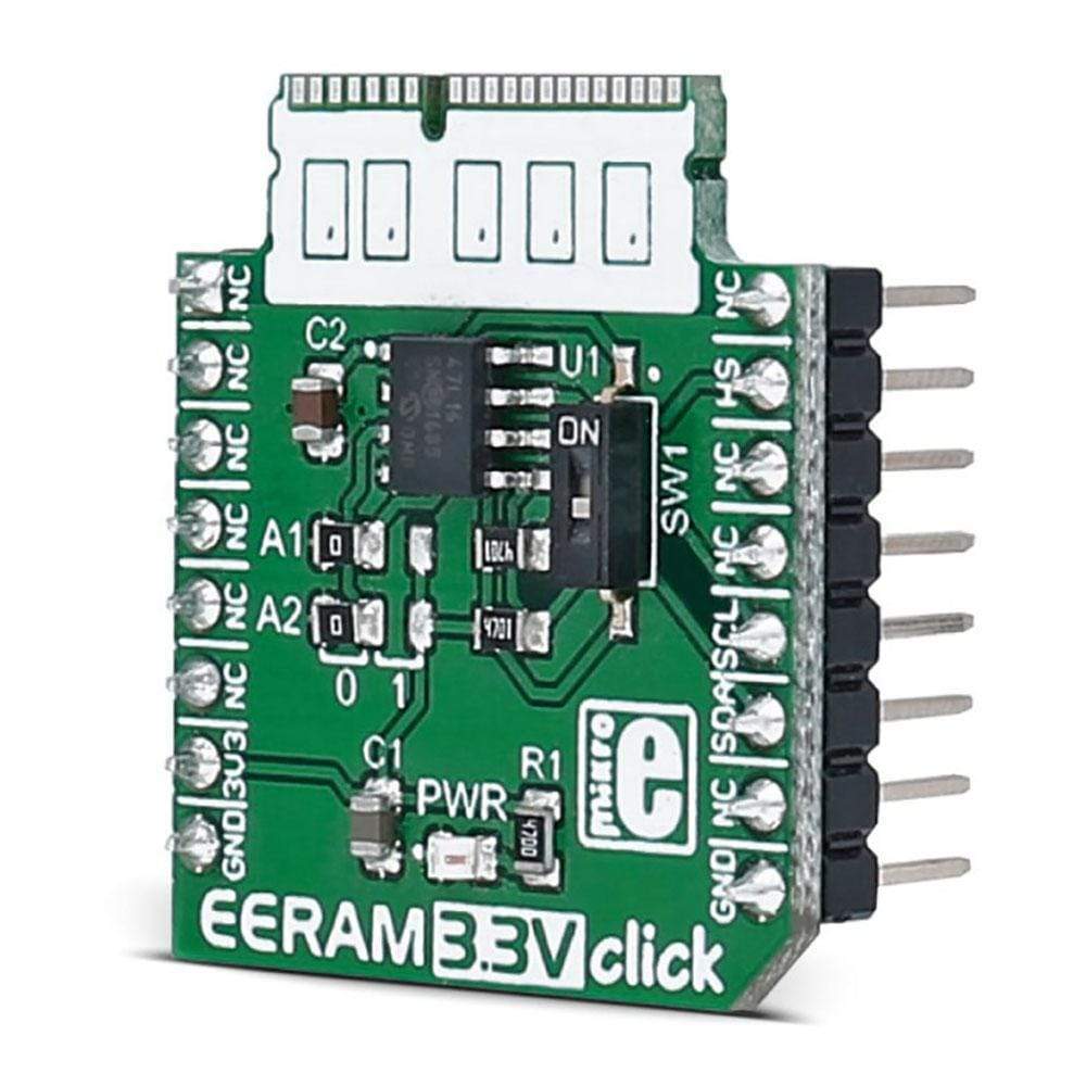
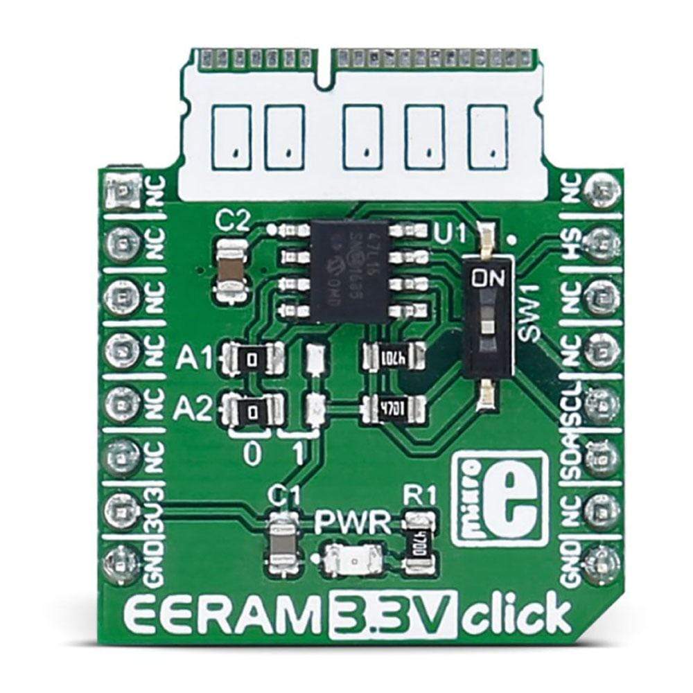
Add memory to your project with EERAM 3.3V Click Board™. It carries the 47L16 EERAM, a 16Kbit SRAM with EEPROM Backup from Microchip. The Click Board™ is designed to run on a 3.3V power supply. It communicates with the target microcontroller over I2C interface, with additional functionality provided by the INT pin on the MikroBUS line.
Downloads
The EERAM 3.3V Click Board™ is a static RAM (SRAM) memory click board™ with the unique feature - it has a backup non-volatile memory array, used to store the data from the SRAM array. Since the SRAM is not able to maintain its content after the power loss, the non-volatile EEPROM backup can be a very handy addition that can be used to preserve the data, even after the power loss event. This is a very useful feature when working with critical or sensitive applications. The memory backup procedure can be executed both automatically and manually. When it is set to work in the manual mode, the onboard capacitor will act as a power source with enough power to complete the backup cycle. The power-on backup restore mode is also available, taking only about 25ms to complete.
The EERAM 3.3V Click Board™ offers combined benefits from both SDRAM and EEPROM worlds. The SDRAM array has zero cycle delay while reading or writing data and infinite read and write cycles, While the EEPROM endures more than one million store cycles and data retention prediction for more than 200 years. With these features, EERAM 3.3V click can be used for a wide range of different applications as the additional memory used to store some sensitive intermediate results of complex calculations, or it can be simply used as the additional semi-volatile SDRAM, for any embedded application. It can be also used to store factory default values, that can be restored on a reset or demand.
How Does The EERAM 3.3V Click Board™ Work?
The EERAM 3.3V Click Board™ uses the 47L16, an I2C serial chip with 16 Kbit and EEPROM backup, from Microchip. The memory cells are organized into 2048 bytes, each 8bit wide. The data is read and written by the I2C serial communication bus, routed to the respective pins of the mikroBUS™ (SCL and SDA pins). To access the device, the first byte sent from the host MCU should be the I2C slave address. In most cases, the master I2C device will be the host MCU itself. The slave IC2 address depends on the state of the hardware address pins on the EERAM 3.3V Click Board™. These pins are routed to the onboard SMD jumpers, labelled as A1 and A2, so they can be pulled either to a HIGH or to a LOW logic level. Besides the address pins, the I2C slave address is determined by the section of the device that needs to be accessed. There are two sections, accessed by a different slave address: SRAM section and the CONTROL REGISTER section. The datasheet of the 47l16 contains more information on these addresses and how to access certain groups of registers. However, provided click library functions allow easy and transparent operation with the EERAM 3.3V Click Board™. The provided example application demonstrates the usage of these library functions, and it can be used as a reference for future custom application development.
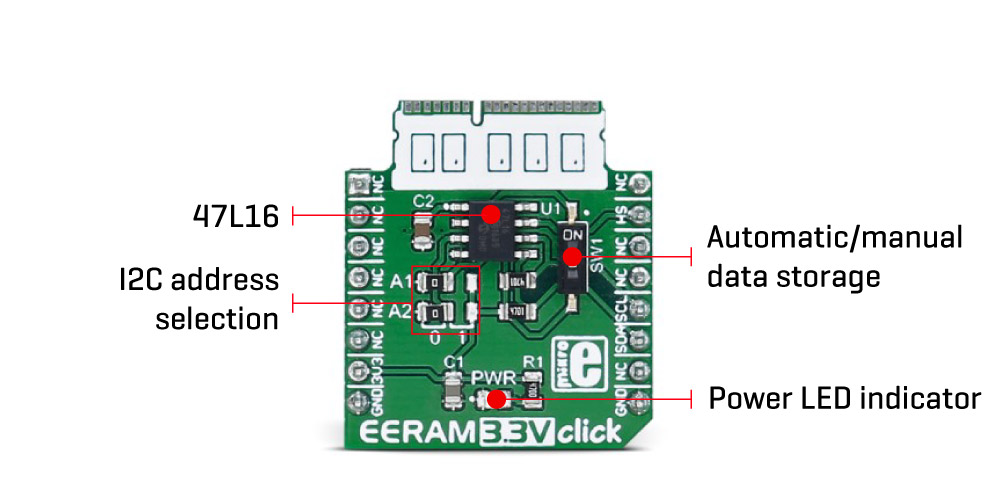
The EERAM 3.3V Click Board™ can backup or restore its content, utilizing the integrated EEPROM non-volatile array, which is not directly accessible. There are several ways to achieve this:
- The most useful method is the auto-store method. To automatically store the data on power loss, the ASE bit of the status register should be set. This will allow the capacitor connected between the VCAP pin of the 47L16 I2C and GND to be used as a temporary power supply (roughly speaking), when the main power is lost (VCAP voltage drops under a certain threshold). It will provide enough power to store the data to the embedded EEPROM array.
- There is a hardware pin on the 47L16 IC, which is used to initiate the hardware (manual) store to EEPROM function. A low-to-high signal edge on the HS pin will cause the backup function to be executed. This pin is routed to the INT pin of the mikroBUS™.
- Auto-restore is initiated after every power on, when the capacitor voltage (VCAP) raises beyond the internally set threshold. It is automatically executed, and no special actions or procedures are needed to trigger this process. A small switch onboard, labelled as SW1 is used to disconnect the VCC power supply from the capacitor, preventing it from being charged and effectively disabling the auto-store and restore functions that way.
The store to EEPROM/backup function will not be executed if the SDRAM content has not been changed since the last time it was written to EEPROM. This is tracked by the AN bit of the status register.
The EERAM 3.3V Click Board™ uses only 3.3V power rail from the mikroBUS™. The I2C lines are pulled to a HIGH logic level by the onboard resistors, so the device is ready to be used with 3.3V MCUs, right out of the box. Although the EERAM 3.3V click is designed to work only with 3.3V MCUs, there is also a 5V alternative version of this device. More information can be found on the product page of the EERAM 5V click.
SPECIFICATIONS
| Type | SRAM |
| Applications | Provides an additional RAM memory for a wide range of embedded applications, especially useful if retaining of the working parameters is required upon the power failure or power off cycle |
| On-board modules | The 47C16 I2C, a serial EERAM from Microchip |
| Key Features | EERAM 3.3V click features 16 Kb of SRAM, with the automatic or manual backup and recall to/from the integrated EEPROM, upon power-down |
| Interface | I2C |
| Compatibility | mikroBUS |
| Click board size | S (28.6 x 25.4 mm) |
| Input Voltage | 3.3V |
PINOUT DIAGRAM
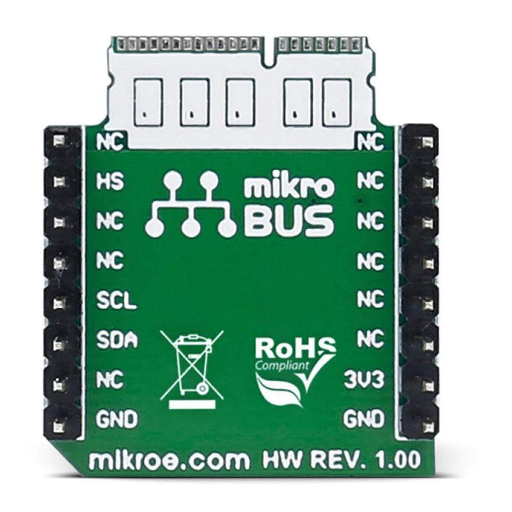
This table shows how the pinout of the EERAM 3.3V Click Board™ corresponds to the pinout on the mikroBUS™ socket (the latter shown in the two middle columns).
| Notes | Pin |  |
Pin | Notes | |||
|---|---|---|---|---|---|---|---|
| NC | 1 | AN | PWM | 16 | NC | ||
| NC | 2 | RST | INT | 15 | HS | HW Store | |
| NC | 3 | CS | TX | 14 | NC | ||
| NC | 4 | SCK | RX | 13 | NC | ||
| NC | 5 | MISO | SCL | 12 | SCL | SCL I2C line | |
| NC | 6 | MOSI | SDA | 11 | SDA | SDA I2C line | |
| Power supply | +3.3V | 7 | 3.3V | 5V | 10 | NC | |
| Ground | GND | 8 | GND | GND | 9 | GND | Ground |
JUMPERS AND SETTINGS
| Designator | Name | Default Position | Default Option | Description |
|---|---|---|---|---|
| JP1 | A1 | Left | 0 | Address select 1 |
| JP2 | A2 | Left | 0 | Address select 2 |
| SW1 | SW1 | Down | OFF | Automatic/manual data store and recall |
BUTTONS AND LEDS
| Designator | Name | Type | Description |
|---|---|---|---|
| LD1 | PWR | LED | Power Indication LED |
| General Information | |
|---|---|
Part Number (SKU) |
MIKROE-2728
|
Manufacturer |
|
| Physical and Mechanical | |
Weight |
0.018 kg
|
| Other | |
Country of Origin |
|
HS Code Customs Tariff code
|
|
EAN |
8606018711130
|
Warranty |
|
Frequently Asked Questions
Have a Question?
Be the first to ask a question about this.


