IqRF Click Board
IqRF Click Board
Key Features
- Selectable RF band 868 / 916 MHz, multiple channels
- Based on the DCTR-76DA RF transceiver from IQRF
- Point-to-point or network wireless connectivity, Telemetry, AMR (automatic meter reading), WSN (wireless sensor network), Building automation, Street lighting control, etc.
- mikroBUS: SPI, UART, Analogue and GPIO Interfaces
Overview
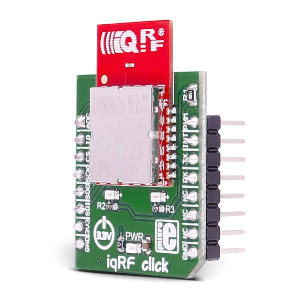
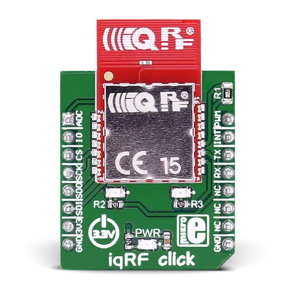
The IQRF Click Board™ is based on the DCTR-76DA RF transceiver, operating in the 868/916 MHz frequency. The Click Board™ is designed to run on a 3.3V power supply. It communicates with the target microcontroller over SPI or UART interface, with additional functionality provided by the following pins on the MikroBUS line: AN, RST, PWM, INT.
The IQRF Click Board™ is based on the DCTR-76DA RF transceiver, operating in the 868/916 MHz frequency. The click is designed to run on a 3.3V power supply. It communicates with the target microcontroller over SPI or UART interface, with additional functionality provided by the following pins on the mikroBUS™ line: AN, RST, PWM, INT.
Module Features
DTCR-76DA is an RF transceiver operating in the 868/916 MHz license-free ISM (Industry, Scientific, and Medical) frequency band. Its highly integrated ready-to-use design containing MCU, RF circuitry, serial EEPROM and optional onboard antenna requires no external components.
How Does The IQRF Click Board™ Work?
RF transceiver modules DCTR-72DA fit in the SIM connector. They are fully programmable under IQRF OS operating system and allow to utilize hardware profiles under DPA framework.
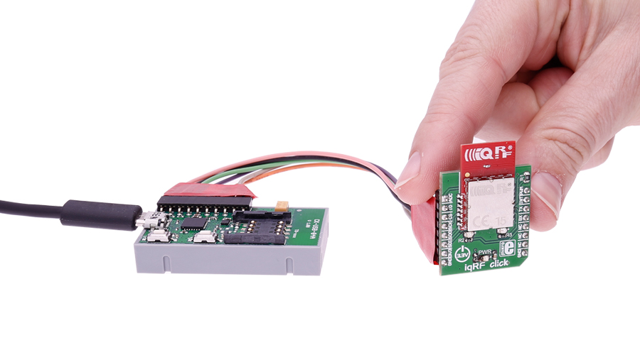
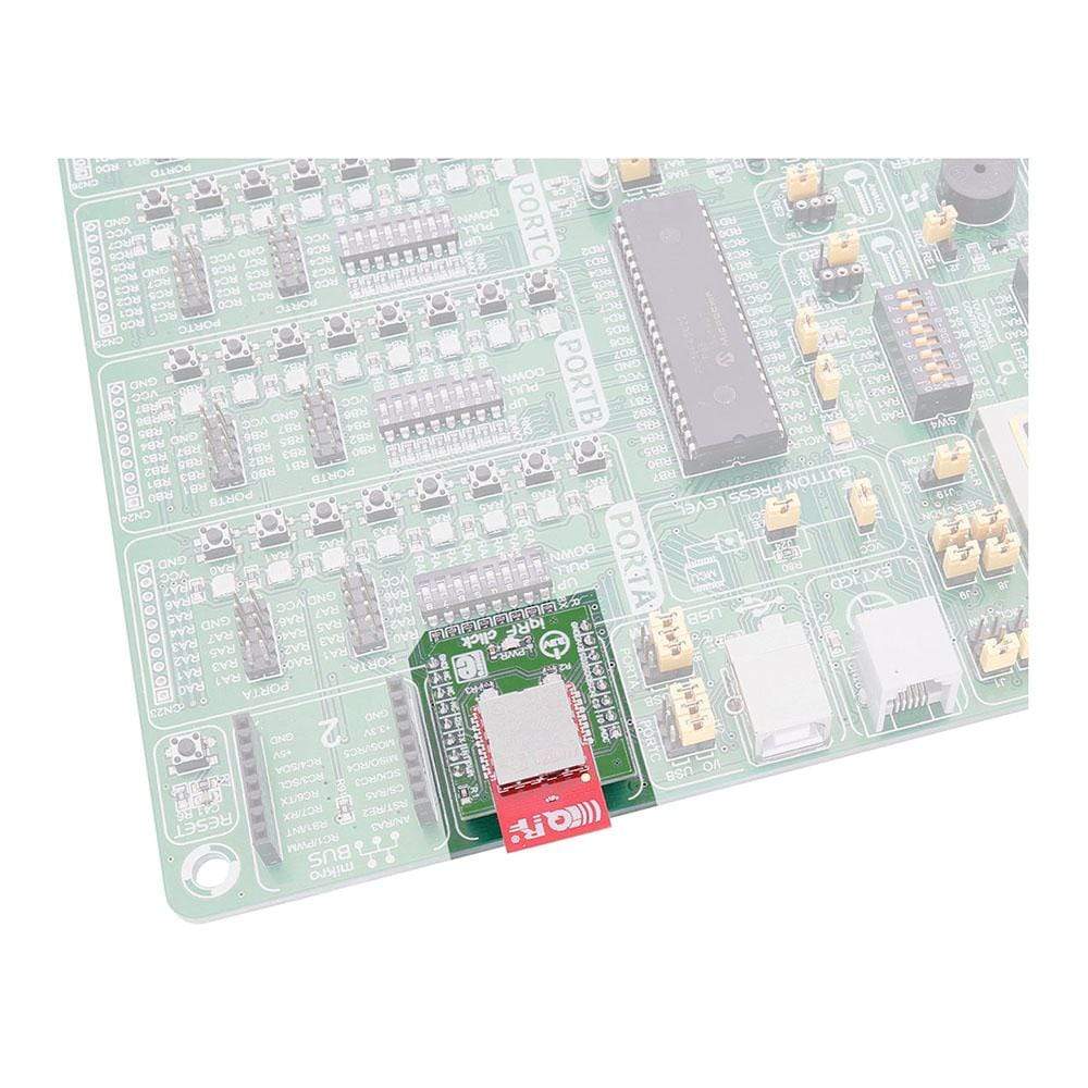
To upload application codes in DCTRs and configure DCTR parameters, CK-USB-04A kit is intended. When the application is uploaded to the IQRF it can be put in microBUS™ socket and communicate with it with MCU.
Specifications
Type | Sub-1 GHz Transceievers |
Applications | Point-to-point or network wireless connectivity, Telemetry, AMR (automatic meter reading), WSN (wireless sensor network), Building automation, Street lighting control, etc. |
On-board modules | DCTR-76DA RF transceiver |
Key Features | Selectable RF band 868 / 916 MHz, multiple channels |
Interface | Analog,GPIO,SPI,UART |
Compatibility | mikroBUS |
Click board size | S (28.6 x 25.4 mm) |
Input Voltage | 3.3V |
Pinout
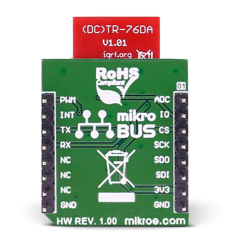
This table shows how the pinout on the IQRF Click Board™ corresponds to the pinout on the mikroBUS™ socket (the latter shown in the two middle columns).
Notes | Pin | Pin | Notes | ||||
---|---|---|---|---|---|---|---|
Analog pin | ADC | 1 | AN | PWM | 16 | DIN | General I/O pin |
General I/O pin | GPIO | 2 | RST | INT | 15 | INT | Interrupt |
SPI enable | SPI_CS | 3 | CS | TX | 14 | TXD | UART transmit |
SPI Clock | SPI_SCK | 4 | SCK | RX | 13 | RXD | UART receive |
SPI Master Input Slave Output | SPI_MISO | 5 | MISO | SCL | 12 | NC | |
SPI Master Output Slave Input | SPI_MOSI | 6 | MOSI | SDA | 11 | NC | |
Power supply | +3.3V | 7 | 3.3V | 5V | 10 | NC | |
Ground | GND | 8 | GND | GND | 9 | GND | Ground |
Software Support
Code examples for the IQRF Click Board™, written for MikroElektronika hardware and compilers are available on Libstock.
Code Snippet
This code snippet contains receiver and transmitter code for the IQRF Click Board™ working with the Thermo K Click Board™. When in transmit mode, MCU reads the temperature from Thermo K and if a certain threshold has been reached, byte data is sent to IQRF board via UART communication. Then, IQRF is broadcasting that byte to every other IQRF within range. Every Other IQRF click board is receiving that byte via RF communication and sending data to his local MCU via UART. Every event is displayed on easyTFT.
01 while(1) 02 { 03 #ifdef __TX__ 04 05 status = &Read_MCP9600_Status; 06 Temp_Data_Ready = (status & 0x40); 07 08 temp = Read_Temperature(); 09 10 if (Temp_Data_Ready) 11 { // Check is Temperature Data ready 12 sprintf(txt, "%2.1f C", temp); // Format Temperature Data and store it to txt 13 res = strcmp(txt,old_txt); // Compare old_txt and txt 14 15 if(res != 0) // If old_txt and txt are not equal 16 { 17 updateLabel(txt, 135, 90, lab1); // Write temperature value on display 18 strcpy(old_txt,txt); // Copy txt to old_txt string array 19 } 20 } 21 22 if (temp <= LOW_TEMP_POINT) // If low temperature point has been reached 23 { 24 if (!low_point_reached) 25 { 26 UART3_Write_Text("L"); // Send byte via UART 27 } 28 low_point_reached = true; 29 30 } 31 else if (temp >= HIGH_TEMP_POINT) // If high temperature point has been reached 32 { 33 if(!high_point_reached) 34 { 35 UART3_Write_Text("H"); // Send byte via UART 36 } 37 high_point_reached = true; 38 39 } 40 else 41 { 42 low_point_reached = false; 43 high_point_reached = false; 44 } 45 Delay_ms(500); 46 #endif 47 48 #ifdef __RX__ 49 50 TFT_Set_Font(&HandelGothic_BT21x22_Regular, CL_BLACK, FO_HORIZONTAL); 51 52 // Writing warnings on display 53 if(high_point_reached) 54 { 55 TFT_Set_Font(&HandelGothic_BT21x22_Regular, CL_RED, FO_HORIZONTAL); 56 high_point_reached = false; 57 TFT_Write_Text("HIGH ", 130, 100); 58 Delay_ms(2000); 59 TFT_Set_Font(&HandelGothic_BT21x22_Regular, CL_WHITE, FO_HORIZONTAL); 60 TFT_Write_Text("HIGH ", 130, 100); 61 } 62 if(low_point_reached) 63 { 64 TFT_Set_Font(&HandelGothic_BT21x22_Regular, CL_BLUE, FO_HORIZONTAL); 65 low_point_reached = false; 66 TFT_Write_Text("LOW", 130, 100); 67 Delay_ms(2000); 68 TFT_Set_Font(&HandelGothic_BT21x22_Regular, CL_WHITE, FO_HORIZONTAL); 69 TFT_Write_Text("LOW ", 130, 100); 70 } 71 #endif 72 } 73 74 }
Frequently Asked Questions
Have a Question?
Be the first to ask a question about this.