Overview
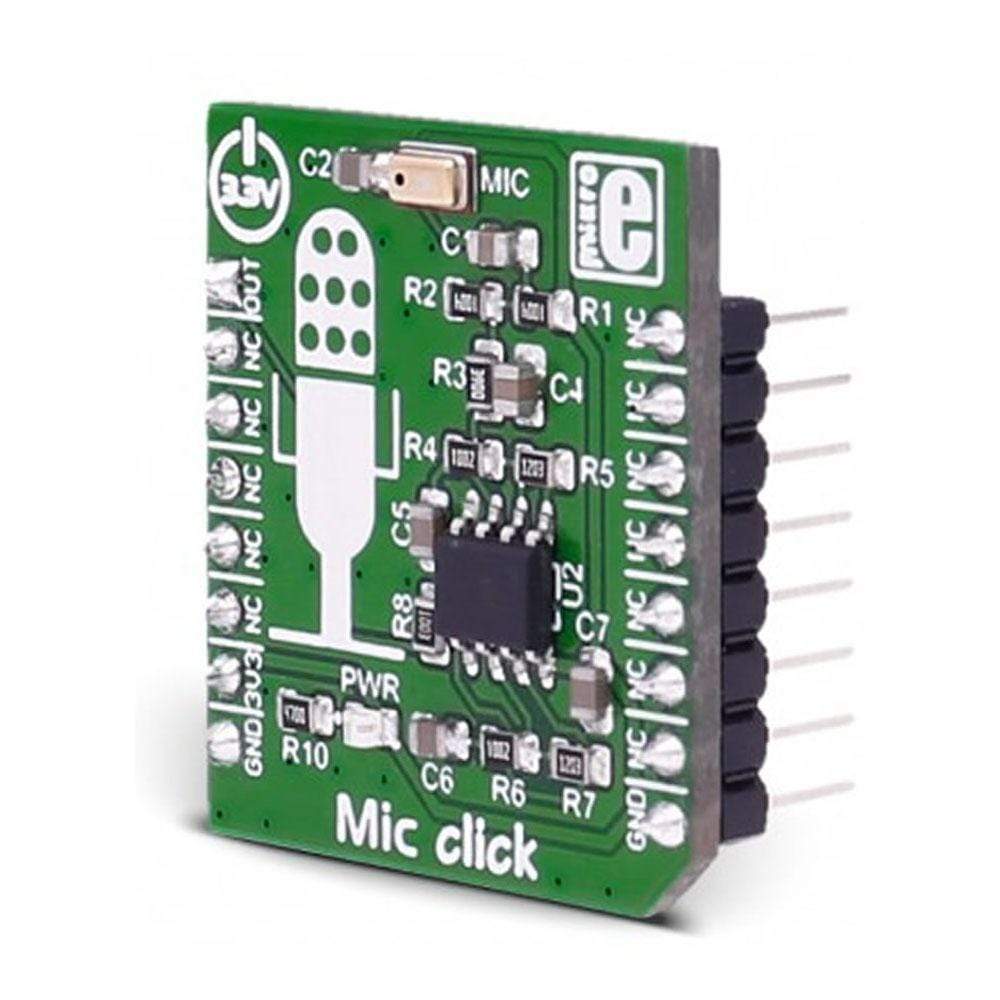
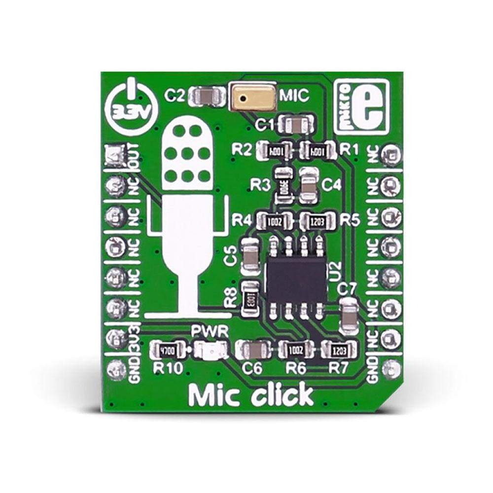
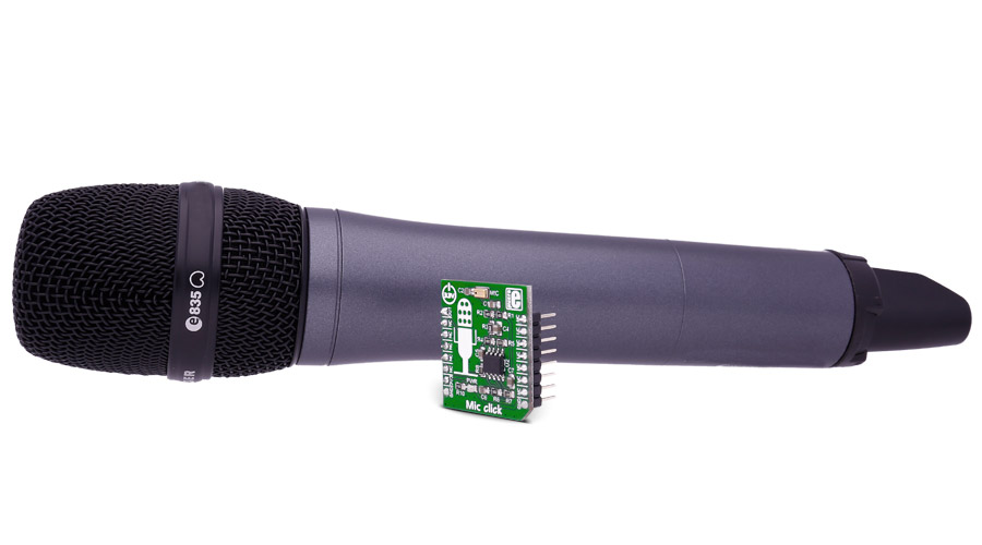
The MIC Click Board™ is based on the SPQ0410HR5H-B surface mount silicon microphone with maximum RF protection.
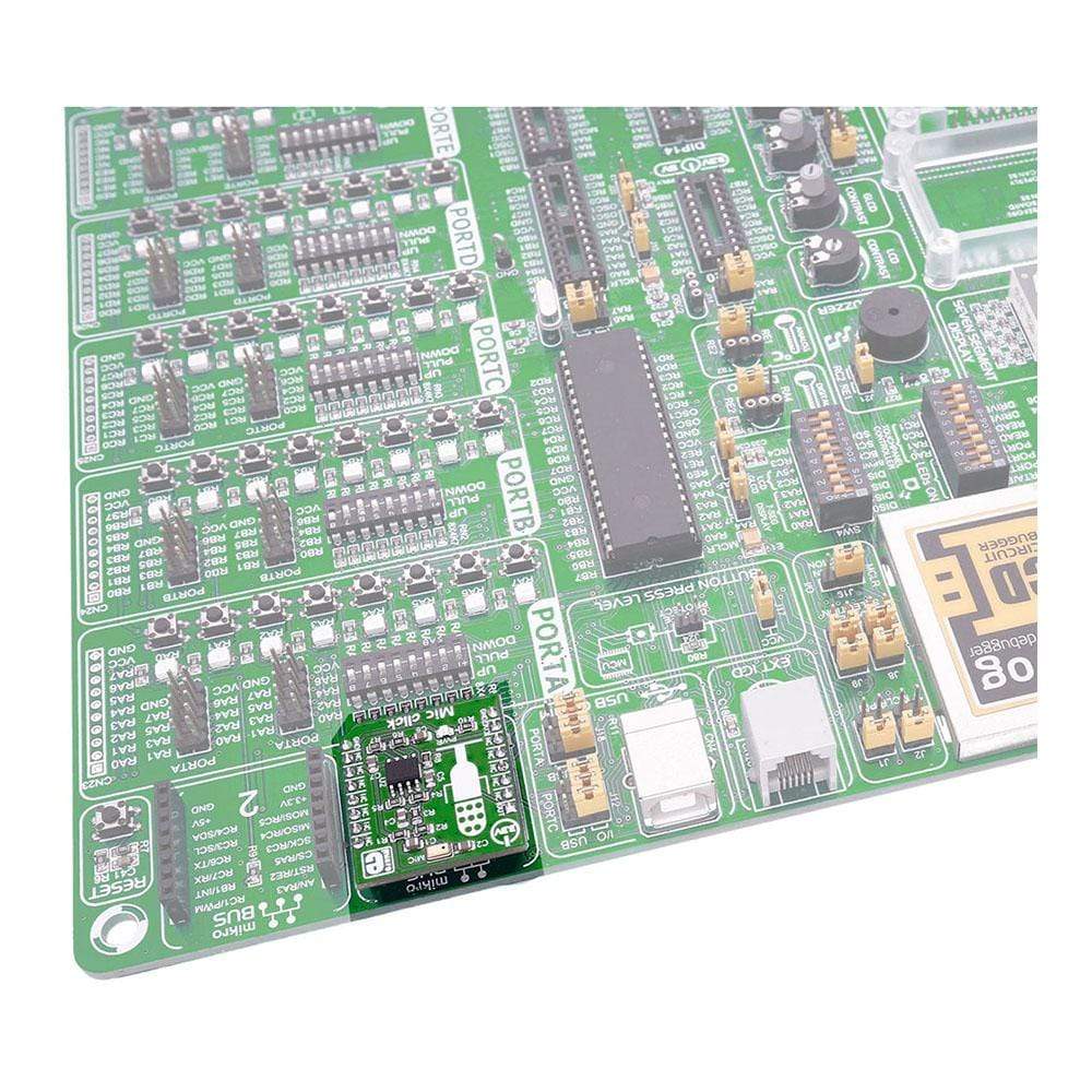
The MIC Click Board™ is designed to run on a 3.3V power supply. It communicates with the target microcontroller over the AN pin on the MikroBUS™ line.
Downloads
The MIC Click Board™ carries the SPQ0410HR5H-B surface mount silicon microphone with maximum RF protection. The click is designed to run on a 3.3V power supply. It communicates with the target microcontroller over the AN pin on the mikroBUS™ line.
How Does The MIC Click Board™ Work?
The MIC Click Board™ contains a silicon microphone, which outputs the signal to the analog pin (AN) on the mikroBUS™ line via the op amp.
SPQ0410HR5H-B FEATURES
The SPQ0410HR5H-B is a miniature, high-performance, low power, top port silicon microphone.
Using the SiSonic™ MEMS technology, the SPQ0410HR5H-B consists of an acoustic sensor, a low noise input buffer, and an output amplifier.
MaxRF protection prevents RF noise in traces from getting into the mic output.
TEST CONDITIONS: 23 ± 2C °, 55 ± 20 % R.H., VDD(min)
| Parameter | Symbol | Conditions | Min | Typ | Max | Units |
|---|---|---|---|---|---|---|
| Supply Voltage1 | VDD | 1.5 | 3.6 | V | ||
| Supply Current1,2 | IDD | 120 | 160 | µA | ||
| Sensitivity1 | S | 94 dB SPL @ 1kHz | -45 | -42 | -39 | dBV/Pa |
| Signal to Noise Ratio | SNR | 94 dB SPL @ 1kHz, A-weighted | 59 | dB(A) | ||
| Total Harmonic Distortion | THD | 94 dB SPL @ 1kHz, S=Typ, Rload>3kΩ | 1 | % | ||
| Acoustic Overload Point | AOP | 10% THD @ 1 kHz, S=Typ, VDD=3.6V, Rload>3kΩ | 115 | dB SPL | ||
| DC Output | VDD=1.5V | 0.73 | V | |||
| Output impedance | ZOUT | @ 1 kHz | 400 | Ω | ||
| Directivity | Omnidirectional | |||||
| Polarity | Increasing sound pressure | Decreasing output voltage | ||||
1100% tested.
2Maximum specifications are measured at maximum VDD. Typical specifications are measured at VDD=1.8V.
OMNIDIRECTIONAL MICROPHONES
SPQ0410HR5H-B is an omnidirectional microphone. As the name implies an omnidirectional microphone can hear equally in all directions. So whichever way you hold it, up or down, it will work the same.
SPECIIFICATIONS
| Type | Microphone |
| Applications | Processing audio with an MCU, mobile phones, smartphones, laptop computers, sensors, digital still cameras, portable music recorders, etc. |
| On-board modules | SPQ0410HR5H-B surface mount silicon microphone with maximum RF protection |
| Key Features | Omnidirectional, MaxRF protection, Sensitivity: -42 dBV/Pa |
| Interface | Analog |
| Compatibility | mikroBUS |
| Click board size | S (28.6 x 25.4 mm) |
| Input Voltage | 3.3V |
PINOUT DIAGRAM
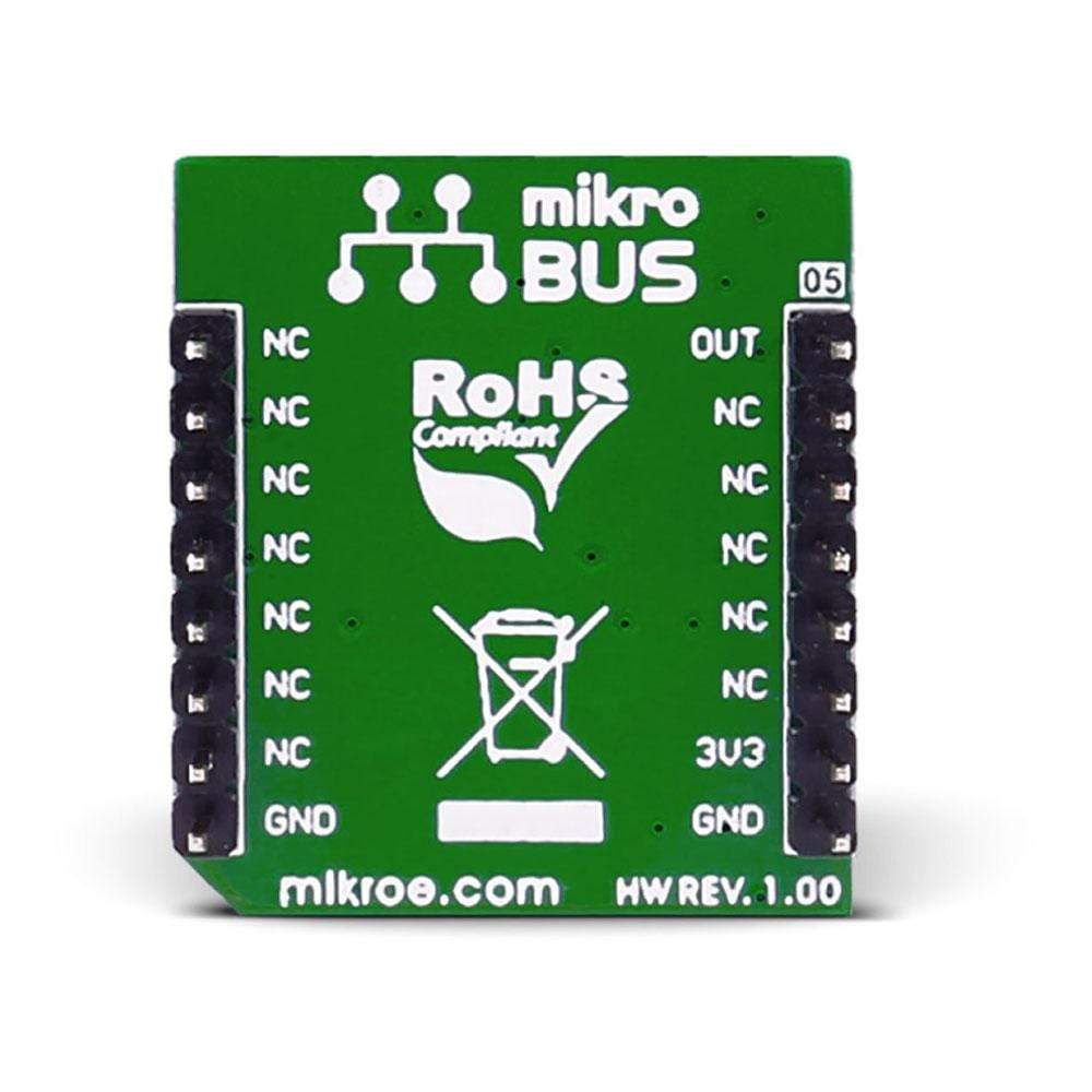
This table shows how the pinout of the MIC Click Board™ corresponds to the pinout on the mikroBUS™ socket (the latter shown in the two middle columns).
| Notes | Pin |  |
Pin | Notes | |||
|---|---|---|---|---|---|---|---|
| Analog output pin | OUT | 1 | AN | PWM | 16 | NC | |
| NC | 2 | RST | INT | 15 | NC | ||
| NC | 3 | CS | TX | 14 | NC | ||
| NC | 4 | SCK | RX | 13 | NC | ||
| NC | 5 | MISO | SCL | 12 | NC | ||
| NC | 6 | MOSI | SDA | 11 | NC | ||
| Power supply | +3.3V | 7 | 3.3V | 5V | 10 | NC | |
| Ground | GND | 8 | GND | GND | 9 | GND | Ground |
| General Information | |
|---|---|
Part Number (SKU) |
MIKROE-2563
|
Manufacturer |
|
| Physical and Mechanical | |
Weight |
0.017 kg
|
| Other | |
Country of Origin |
|
HS Code Customs Tariff code
|
|
EAN |
8606018710386
|
Warranty |
|
Frequently Asked Questions
Have a Question?
Be the first to ask a question about this.


