Grid-EYE Click Board
Overview
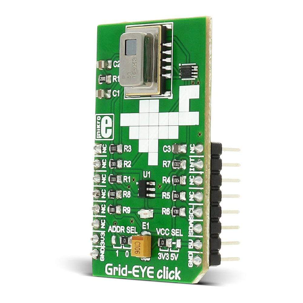
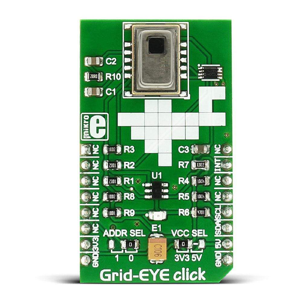
The Grid-EYE Click Board™ is an 8x8 thermal array sensor-detector that carries the AMG8853 infrared array sensor from Panasonic.
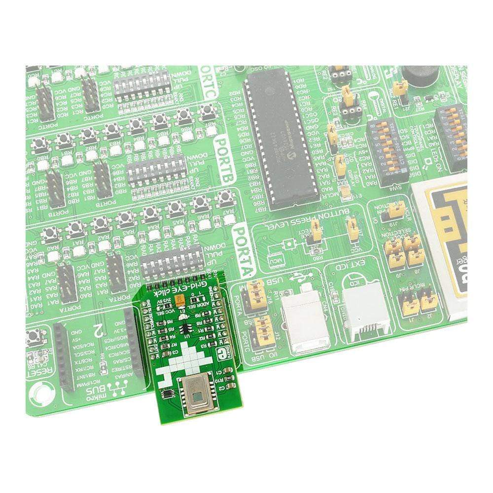
The Click Board™ is designed to run on either a 3.3V or 5V power supply. It communicates with the target MCU over the I2C interface.
Use the Grid-EYE Click Board™ to detect absolute surface temperature without any contact. Or use it to detect the movement of people and objects.
The Grid-EYE Click Board™ is a 8x8 thermal array sensor-detector that carries the AMG8853 infrared array sensor from Panasonic. The click is designed to run on either 3.3V or 5V power supply. It communicates with the target MCU over I2C interface.
Use the Grid-EYE Click Board™ to detect absolute surface temperature without any contact. Or use it to detect the movement of people and objects.
Take a look at how Panasonic's AMG8853 64 thermal sensors see a moving hand:
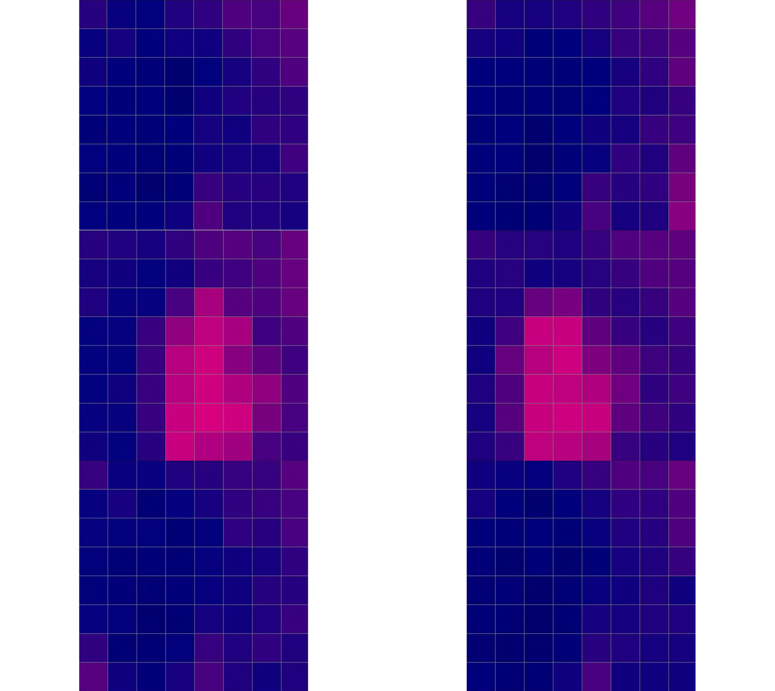
AMG8853 SENSOR FEATURES
The AMG8853 is made out of 64 individual thermal sensors. It can build an image according to the heat it detects. You don't need light to form a picture.
The temperature measuring range is from -20°C to +100°C.
The detecting distance is 5m, the viewing angle 60 degrees.
The AMG8853 has a built-in thermistor for suppressing ambient temperature noise.
The I2C levels and address are jumper selectable, while the AMG8853 is supplied with designated voltage.
INFRARED SENSOR
Infrared waves are outside the visible spectrum of the human eye, just like radio waves. Even though people can't see infrared waves, they can certainly feel them, in the form of heat.
Our bodies emit heat or infrared radiation, and the AMG8853 thermal array sensor can detect it.
SPECIFICATIONS
Type | Temperature & humidity |
Applications | Thermal imaging systems, detecting movement of people and objects, etc |
On-board modules | AMG8853 thermal array sensor from Panasonic |
Key Features | 5 m detecting distance, 60 degrees viewing angle, 64 individual thermal sensors |
Interface | GPIO,I2C |
Compatibility | mikroBUS |
Click board size | M (42.9 x 25.4 mm) |
Input Voltage | 3.3V or 5V |
PINOUT DIAGRAM
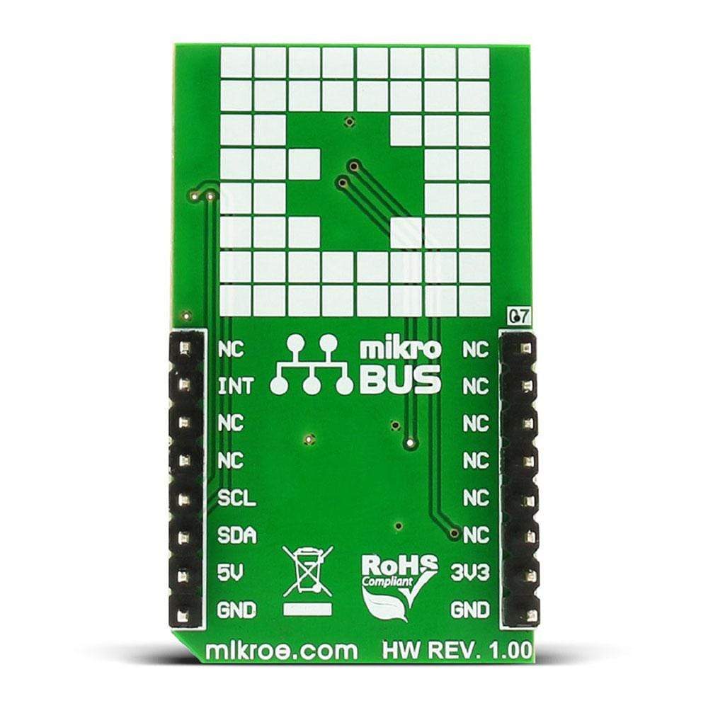
This table shows how the pinout of the Grid-EYE Click Board™ corresponds to the pinout on the mikroBUS™ socket (the latter shown in the two middle columns).
Notes | Pin | Pin | Notes | ||||
---|---|---|---|---|---|---|---|
NC | 1 | AN | PWM | 16 | NC | ||
NC | 2 | RST | INT | 15 | INT | INT out to MCU | |
NC | 3 | CS | TX | 14 | NC | ||
NC | 4 | SCK | RX | 13 | NC | ||
NC | 5 | MISO | SCL | 12 | SCL | I2C SCK | |
NC | 6 | MOSI | SDA | 11 | SDA | I2C data | |
Power supply | +3.3V | 7 | 3.3V | 5V | 10 | +5V | Power supply |
Ground | GND | 8 | GND | GND | 9 | GND | Ground |
JUMPERS AND SETTINGS
Designator | Name | Default Position | Default Option | Description |
---|---|---|---|---|
JP1 | LOGIC SEL | Left | 3.3V | Logic Level Voltage Selection, left position 3.3V, right position 5V |
JP2 | ADDR SEL | Right | 0 | I2C address selection, right 0 (0b1101 000) Left 1 (0b1101 001) |
BUTTONS AND LEDS
Designator | Name | Type | Description |
---|---|---|---|
PWR | Power | LED | Power supply LED, lights green when power is on. |
MAXIMUM RATINGS
Description | Min | Typ | Max | Unit |
---|---|---|---|---|
Supply Voltage (with AMG8853 module) | 5 | 5 | V | |
I2C Levels (JP1 select) | 0 | 5 | V | |
INT out (JP1 select) | 0 | 5 | V |
Software Support
Code examples for the Grid-EYE Click Board™, written for MikroElektronika hardware and compilers are available on Libstock.
CODE SNIPPET
This code converts the grid array sensor data to temperature [in C] and fills the grid array drawn on the TFT display by the appropriate color, depending on the temperature detected.
01 void main() { 02 // Initialize pins as digital I/O 03 AD1PCFG = 0xFFFF; 04 JTAGEN_bit = 0; 05 06 // Initialize I2C2 module 07 I2C2_Init(100000); 08 Delay_ms(100); 09 10 // Draw screen 11 DrawScreen(); 12 13 // variable declaration 14 x_start = 80; 15 element_dimension = 20; 16 j = 0; 17 18 // Set AMG88 sensor registers 19 GridEye_WriteByte(0x00,0x00); // Normal mode 20 GridEye_WriteByte(0x01,0x30); // Flag reset 21 GridEye_WriteByte(0x02,0x00); // Frame mode 10FPS 22 Delay_ms(100); // small delay 23 24 GridEye_WriteByte(0x08,0x30); // INTHL 25 GridEye_WriteByte(0x09,0x00); // INTHH 26 27 GridEye_WriteByte(0x0A,0x15); // INTLL 28 GridEye_WriteByte(0x0B,0x00); // INTLH 29 30 GridEye_WriteByte(0x0C,0x20); // IHYSL 31 GridEye_WriteByte(0x0D,0x00); // IHYSH 32 Delay_ms(100); // small delay 33 34 // Temperature register value 35 register_address = 0x80; 36 37 while(1) { 38 // Reading grid temperature 39 for(i = 0; i < 64; i++) { 40 // multiply the values with 0.25 to get temperature in [C] 41 gridArray[i] = (float)GridEye_ReadWord(register_address) * 0.25L; 42 // increment register address by 2 43 register_address = register_address + 2; 44 } 45 46 // draw grid 47 for(i = 0; i < 64; i++) { 48 // set row position 49 Set_Row_Position(); 50 51 // set color 52 color = Set_Color(); 53 54 // set grid element number 55 j++; 56 57 // fill grid element with color 58 TFT_Set_Brush(1, 0, 1, LEFT_TO_RIGHT, color, color); 59 60 // draw grid element 61 TFT_Rectangle(x_start + (element_dimension * (j - 1)), y_start , x_start + (element_dimension * j), y_end); 62 63 // if more than 8 elements in the row, reset counter 64 if (j >= 8) { 65 j = 0; 66 } 67 } 68 } 69 }
Frequently Asked Questions
Have a Question?
Be the first to ask a question about this.