Overview
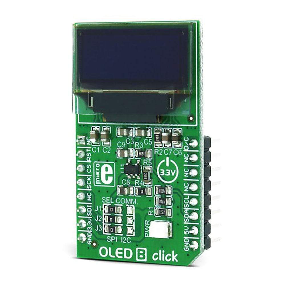
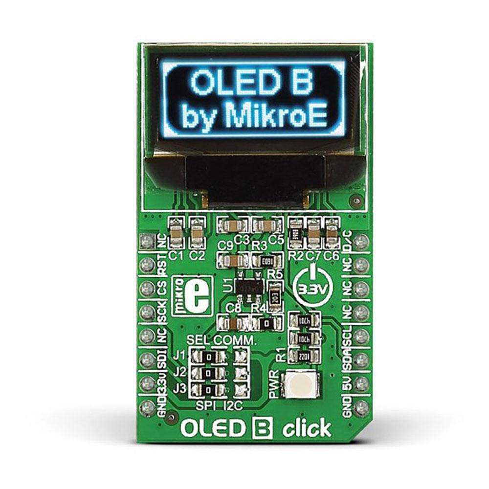
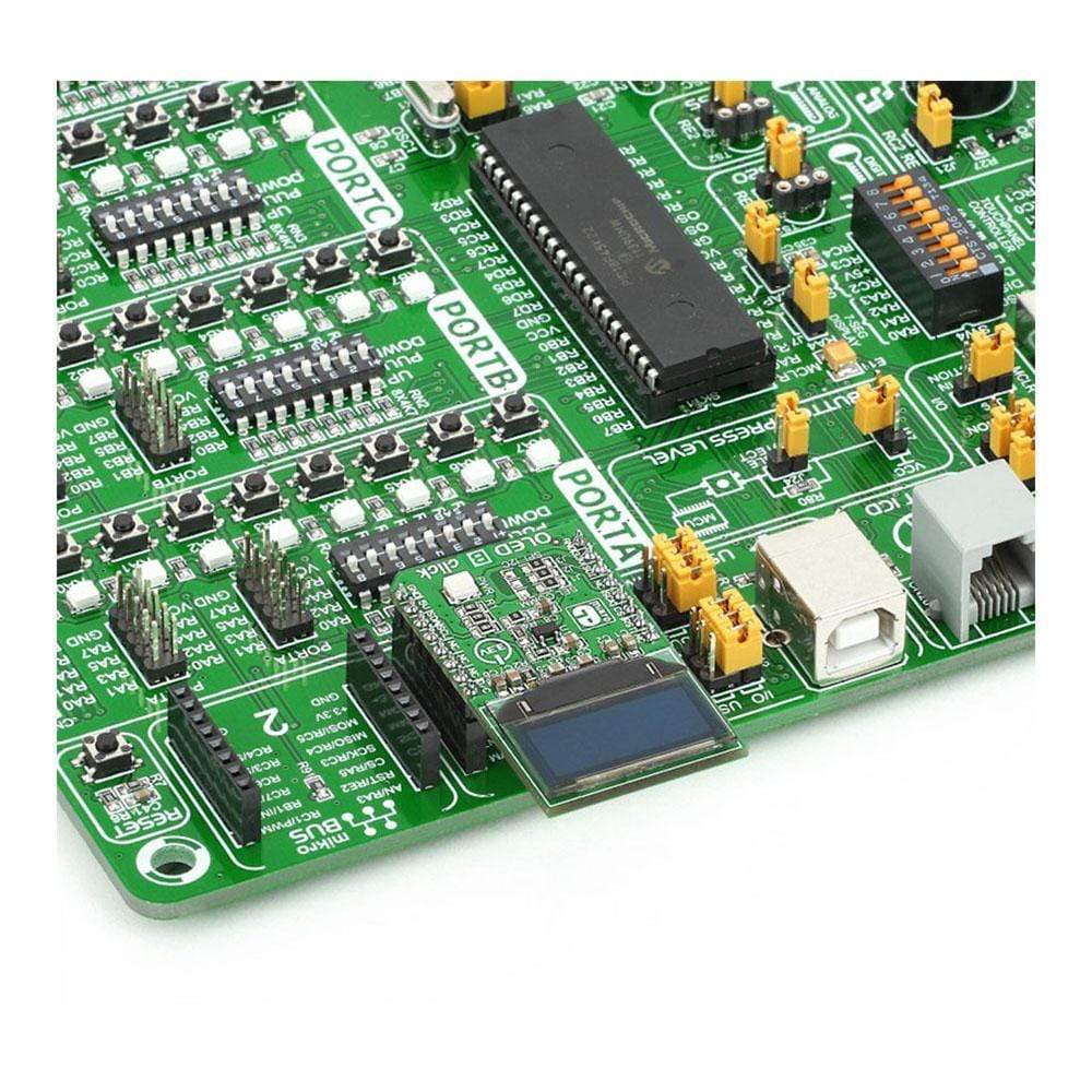
The OLED B Click Board™ is a display board with a blue monochrome passive-matrix OLED display. This bright and clear 96x39 pixel display is designed to be viewable from wide angles. Controlled by SSD1306 controller, OLED B Click Board™ offers a range of functionalities, including horizontal and vertical scrolling, contrast control, normal or inverse image display and more. The Click Board™ uses SPI or I2C MikroBUS lines to communicate with the target board microcontroller. The interface outputs can be chosen by resoldering three jumpers to the appropriate position. In spite of a sharp, high-contrast display,
The OLED B Click Board™ operates on low power consumption. It is an ideal choice for displaying lines of text or icons. This module uses a 3.3V power supply only.
Downloads
How Does The OLED B Click Board™ Work?
The OLED B Click Board™ as its foundation uses the MI9639BO-B2, a 19.3x7.8mm 96x39px light blue monochrome passive matrix OLED display from Multi-Inno Technology. The MI9639BO-B2 display features an SSD1306, a 128x64 dot-matrix OLED/PLED segment/common driver with a controller. The controller has built-in functionalities like contrast control (256-step brightness control), normal or inverse image display, vertical and horizontal scrolling functions, and much more accessible through the I2C serial interface.
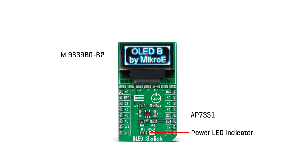
OLEDs are emissive and don't require a separate backlight as LCD technology does, reducing the OLED display's overall power consumption compared to LCDs. It also does not suffer from loss of contrast due to bleed-through of the backlight in the "off" pixels. OLEDs, being emissive, have a consistent contrast ratio greater than 100:1 with no limitation in viewing angle. In addition, they don't suffer from temperature-related response time delays and contrast changes.
Like any OLED display, the MI9639BO-B2 is made from a thin film of an organic compound that emits light when exposed to a current. A small monochrome display like this one represents an ideal solution for displaying text or icons. The MI9639BO-B2 display is bright, has a wide viewing angle, and low power consumption.
In addition to the display's main power supply, taken from the +3.3V microBUS™ power rail, the MI9639BO-B2 has another power pin, more precisely the power supply for DC/DC converter circuit. This pin is the power supply pin for the internal buffer of the DC/DC voltage converter. Therefore, for this pin, the Click board™ uses a low dropout linear regulator AP7331 from Diodes Incorporated, providing a 3.6V power supply out of 5V mikroBUS™ rail.
The OLED B Click Board™ communicates with MCU using the standard I2C 2-Wire interface to read data and configure settings. It provides the possibility of the communication-enable feature routed to the CS pin of the mikroBUS™ socket, enabling the OLED B Click for MCU communication only when the CS pin is pulled to a low logic state. In addition, it has two more pins. First is related to the reset function, routed to the RST pin on the mikroBUS™ socket (when the pin is in a low logic state, the initialization of the chip is executed), and the second labelled as D/C and routed to the PWM pin on the mikroBUS™ socket is I2C slave address selection pin.
NOTE: If the noise accidentally occurs at the displaying window during the operation, please reset the display to recover the display function.
The OLED B Click Board™ is designed to be operated only with a 3.3V logic voltage level, while 5V is used as a supply voltage of the AP7331 LDO. The board must perform appropriate logic voltage level conversion before use with MCUs with different logic levels. However, the Click board™ comes equipped with a library containing easy-to-use functions and an example code that can be used, as a reference, for further development.
SPECIFICATIONS
| Type | OLED |
| Applications | The OLED B Click Board™ is Ideal for displaying bright and crisp blue text or icons |
| On-board modules | SSD1306 controller, 96 x 39px blue monochrome passive matrix OLED display |
| Key Features | 96 x 39px resolution, 19.3 x 7.8mm active area |
| Interface | GPIO,I2C,SPI |
| Compatibility | mikroBUS |
| Click board size | M (42.9 x 25.4 mm) |
| Input Voltage | 3.3V,5V |
PINOUT DIAGRAM
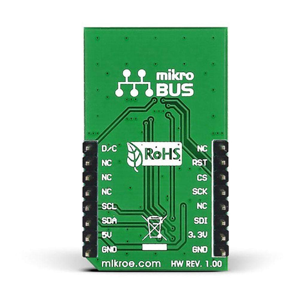
This table shows how the pinout of the OLED B Click Board™ corresponds to the pinout on the mikroBUS™ socket (the latter shown in the two middle columns).
| Notes | Pin |  |
Pin | Notes | |||
|---|---|---|---|---|---|---|---|
| NC | 1 | AN | PWM | 16 | D/C | I2C Slave Address Selection | |
| Reset | RST | 2 | RST | INT | 15 | NC | |
| Communication Enable | CS | 3 | CS | RX | 14 | NC | |
| NC | 4 | SCK | TX | 13 | NC | ||
| NC | 5 | MISO | SCL | 12 | SCL | I2C Clock | |
| NC | 6 | MOSI | SDA | 11 | SDA | I2C Data | |
| Power Supply | 3.3V | 7 | 3.3V | 5V | 10 | 5V | Power Supply |
| Ground | GND | 8 | GND | GND | 9 | GND | Ground |
ONBOARD SETTINGS AND INDICATORS
| Label | Name | Default | Description |
|---|---|---|---|
| LD1 | PWR | - | Power LED Indicator |
OLED B CLICK ELECTRICAL SPECIFICATIONS
| Description | Min | Typ | Max | Unit |
|---|---|---|---|---|
| Receiver inputs voltage range | 3.3 | - | 5 | V |
| Receiver inputs voltage range | - | 96(H) x 39(V) | - | px |
| Receiver inputs voltage range | -40 | +25 | +70 | °C |
| General Information | |
|---|---|
Part Number (SKU) |
MIKROE-1650
|
Manufacturer |
|
| Physical and Mechanical | |
Weight |
0.035 kg
|
| Other | |
Country of Origin |
|
HS Code Customs Tariff code
|
|
EAN |
8606015075556
|
Warranty |
|
Frequently Asked Questions
Have a Question?
Be the first to ask a question about this.


