Overview
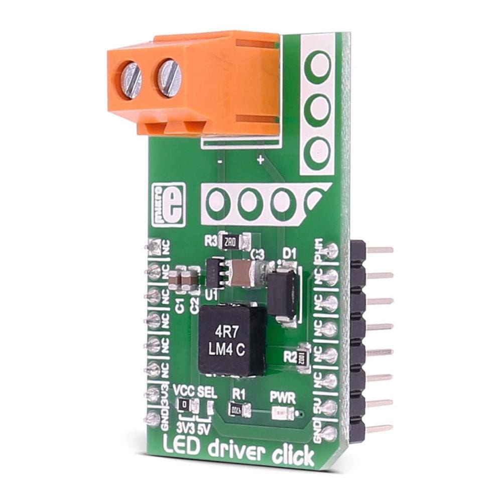
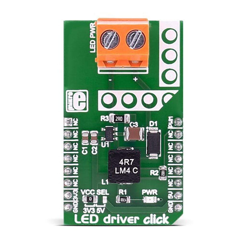
The LED Driver Click Board™ is based on the MCP1662 high-voltage step-up voltage driver from Microchip. The Click Board™ is designed to run on either 3.3V or 5V power supply. It communicates with the target microcontroller over PWM pin on the MikroBUS line.
Downloads
The LED Driver Click Board™ carries the MCP1662 high-voltage step-up voltage driver from Microchip. The LED Driver Click Board™ is designed to run on either 3.3V or 5V power supply. It communicates with the target microcontroller over PWM pin on the mikroBUS™ line.
MCP1662 MCU FEATURES
The MCP1662 device is a compact, space-efficient, fixed-frequency, non-synchronous step-up converter optimized to drive LED strings with a constant current from a two- or three-cell alkaline or lithium Energizer®, or NiMH/NiCd, or one-cell Lithium-Ion or Li-Polymer batteries.
The device integrates a 36V, 800 mW low-side switch, which is protected by the 1.3A cycle-by-cycle inductor peak current limit operation.
How Does The LED Driver Click Board™ Work?
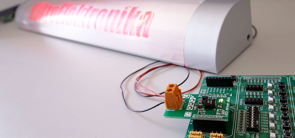
The LED Driver Click Board™ has a power input and a PWM input, so the LED lights can be dimmed. It's a great choice for driving LED strips.
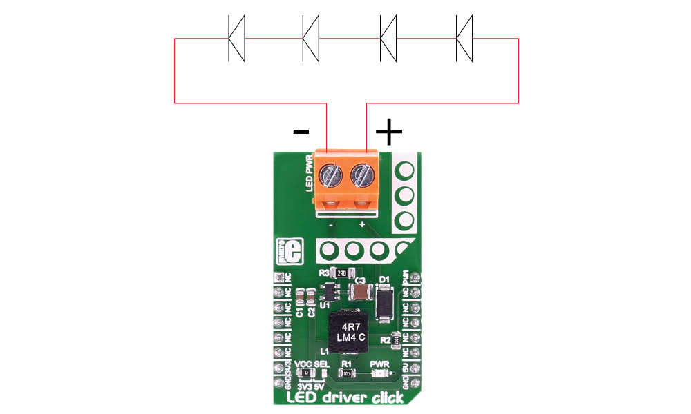
SPECIFICATIONS
| Type | LED Drivers |
| Applications | LED strings with a constant current from a two- or three-cell alkaline or lithium Energizer®, or NiMH/NiCd, or one-cell Lithium-Ion or Li-Polymer batteries |
| On-board modules | MCP1662 High-Voltage Step-Up LED Driver |
| Key Features | Open Load Protection, Overtemperature Protection, Input Voltage Range: 2.4V to 5.5V |
| Interface | PWM |
| Compatibility | mikroBUS |
| Click board size | M (42.9 x 25.4 mm) |
| Input Voltage | 3.3V or 5V |
PINOUT DIAGRAM
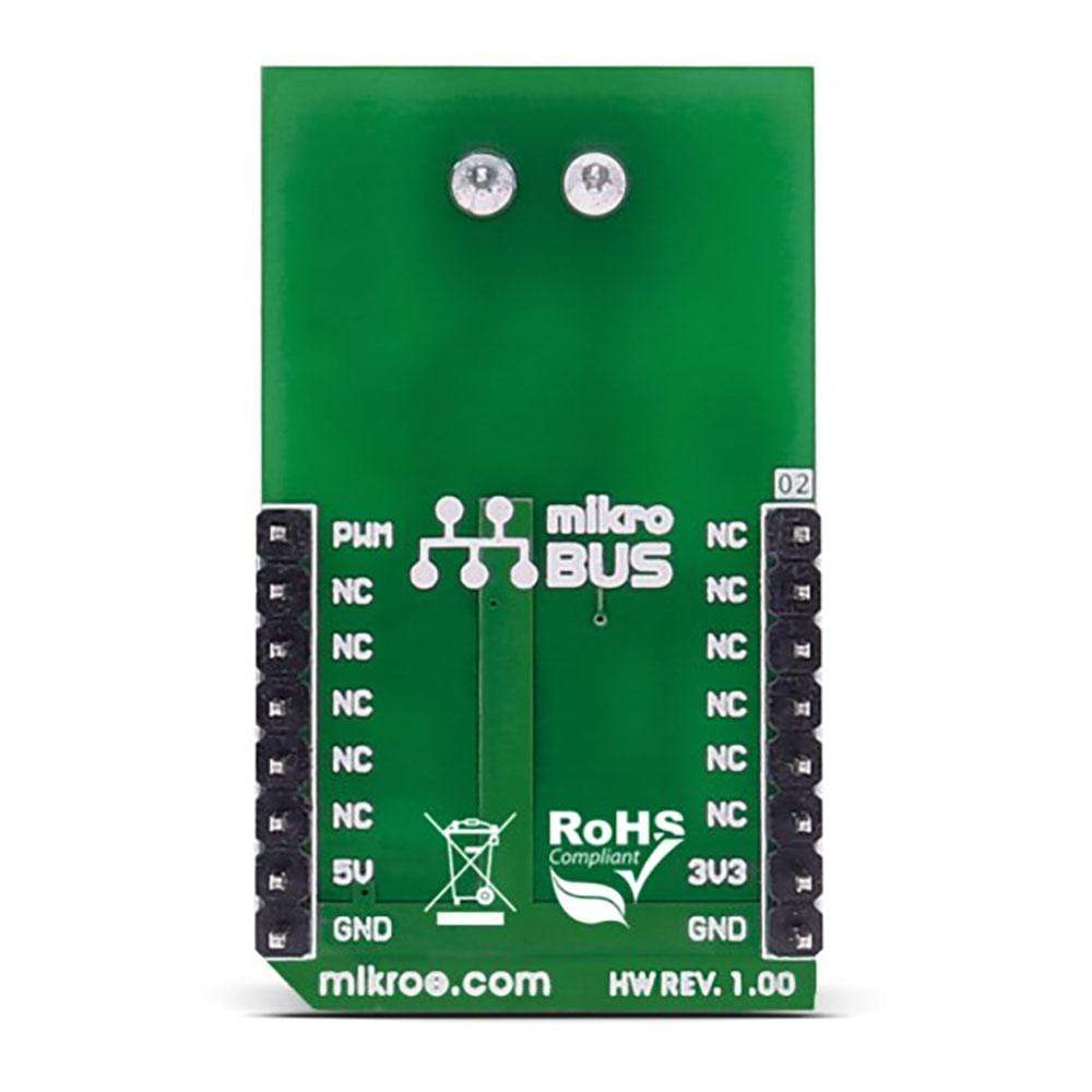
This table shows how the pinout on the LED Driver Click Board™ corresponds to the pinout on the mikroBUS™ socket (the latter shown in the two middle columns).
| Notes | Pin |  |
Pin | Notes | |||
|---|---|---|---|---|---|---|---|
| NC | 1 | AN | PWM | 16 | PWM | PWM input | |
| NC | 2 | RST | INT | 15 | NC | ||
| NC | 3 | CS | TX | 14 | NC | ||
| NC | 4 | SCK | RX | 13 | NC | ||
| NC | 5 | MISO | SCL | 12 | NC | ||
| NC | 6 | MOSI | SDA | 11 | NC | ||
| Power supply | +3.3V | 7 | 3.3V | 5V | 10 | +5V | Power supply |
| Ground | GND | 8 | GND | GND | 9 | GND | Ground |
MAXIMUM RATINGS
| Description | Min | Typ | Max | Unit |
|---|---|---|---|---|
| Supply Voltage | 2.4 | 5.5 | V | |
| Max Out Voltage | 32 | V | ||
| Max Out Current 4.2V Vin 8 LEDs | 100 | mA | ||
| Max Out Current 3.3V Vin 4 LEDs | 125 | mA | ||
| Max Out Current 5.0V Vin 4 LEDs | 200 | mA |
| General Information | |
|---|---|
Part Number (SKU) |
MIKROE-2676
|
Manufacturer |
|
| Physical and Mechanical | |
Weight |
0.021 kg
|
| Other | |
Country of Origin |
|
HS Code Customs Tariff code
|
|
EAN |
8606018710867
|
Warranty |
|
Frequently Asked Questions
Have a Question?
Be the first to ask a question about this.

