

SEGGER Microcontroller GmbH
SEGGER 9-Pin Cortex-M Adapter (SKU 8.06.02)
SEGGER 9-Pin Cortex-M Adapter (SKU 8.06.02)
SKU: 8.06.02
Couldn't load pickup availability

Key Features
Overview
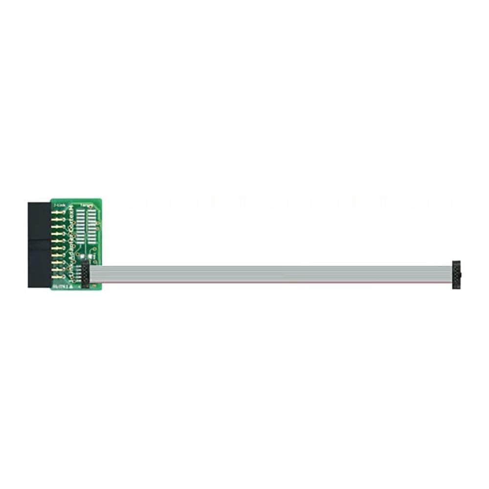
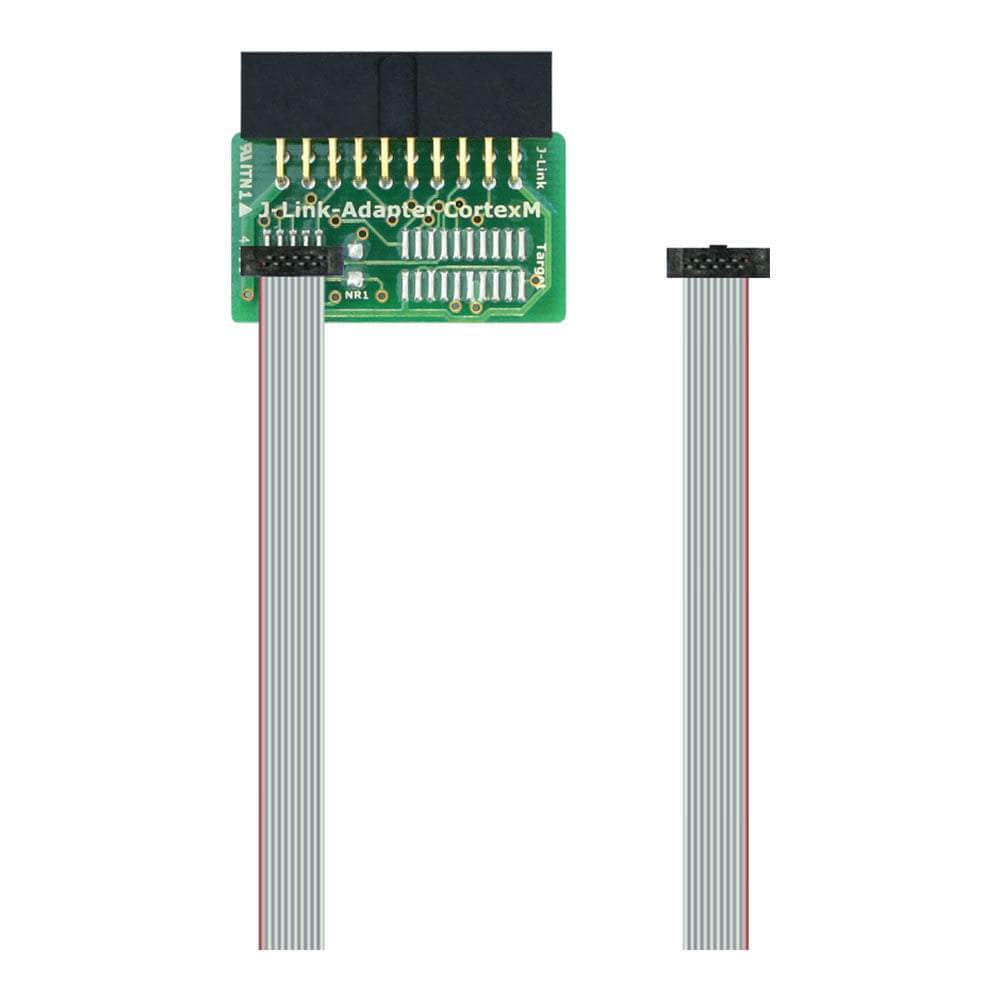
The SEGGER 9‑Pin Cortex‑M Adapter (8.06.02) converts the standard 20‑pin 0.1″ J-Link/Flasher connector to the compact 9‑pin 0.05″ Cortex‑M header widely used on modern microcontroller boards. It supports SWD, JTAG, and SWO, and ships with a matching 9‑pin cable for immediate use. By default TRST is not connected, but a solder bridge (NR1) allows optional TRST routing to pin 9 for targets that require it. This adapter is part of SEGGER’s broad accessory range covering 2 mm, 14‑pin TI, 19‑pin Cortex‑M, and other target ecosystems.
Looking for the product on Debug Store? See the current 9‑Pin Cortex‑M Adapter page and related J‑Link accessories.
Compatible with J‑Link BASE/PLUS/ULTRA+/PRO (Classic/Compact), J‑Link WiFi, and Flasher programmers; also usable with non‑Cortex‑M targets if the target exposes the same 9‑pin pinout.
Downloads
Why Engineers Choose The SEGGER 9-Pin Cortex-M Adapter (SKU 8.06.02)
Standards‑compliant wiring
Flexible reset options
Proven J‑Link ecosystem
SEGGER 9-Pin Cortex-M Adapter
Adapts the 20-pin 0.1″ J-Link/Flasher header to the 9-pin 0.05″ Cortex‑M Samtec FTSH footprint for SWD, JTAG and SWO. Includes 9-pin ribbon cable. [SKU: 8.06.02]
The SEGGER 9-Pin Cortex‑M Adapter enables reliable JTAG, SWD, and SWO connections from any compatible J-Link or Flasher probe to targets that provide the compact 9‑pin 0.05″ Cortex‑M header defined by Arm. It converts the standard 20‑pin 0.1″ ribbon from the probe to the 9‑pin fine‑pitch Samtec FTSH connector used on many modern MCU boards. [SKU: 8.06.02]
Key terms (plain definitions): VTref — target I/O level reference used by the probe to match logic levels; SWD — two‑wire Arm Serial Wire Debug (SWDIO, SWCLK); SWO — Serial Wire Output trace pin; JTAG — 4/5‑wire IEEE 1149.1 debug; nRESET — active‑low target reset line; TRST — optional JTAG reset. [SKU: 8.06.02]
Compatibility
- Works with J-Link BASE/PLUS/ULTRA+/PRO, J-Link WiFi/Compact, and SEGGER Flasher units that expose the 20‑pin 0.1″ connector. [SKU: 8.06.02]
- Targets must provide the 9‑pin Samtec FTSH Cortex‑M pinout; non‑Cortex‑M targets are supported if the same 9‑pin pinout is used. [SKU: 8.06.02]
- TRST is not connected by default; solder bridge NR1 can route TRST to pin 9 when needed for JTAG. [SKU: 8.06.02]
Pinout (9‑pin Cortex‑M header)
| Pin | Signal | Direction | Description |
|---|---|---|---|
| 1 | VTref | Input | Target reference voltage for level matching and power‑present sense. |
| 2 | SWDIO / TMS | I/O / Out | SWD data or JTAG TMS. |
| 3 | GND | Ground | Digital ground. |
| 4 | SWCLK / TCK | Out | SWD clock or JTAG TCK. |
| 5 | GND | Ground | Digital ground. |
| 6 | SWO / TDO | Input | SWO trace (SWD) or JTAG TDO. |
| (7) | Key | — | Key location; physically not populated. |
| 8 | NC / TDI | NC / Out | Not used for SWD; JTAG TDI when applicable. |
| 9 | NC (TRST) | NC | Optional TRST if NR1 solder bridge is closed. |
| 10 | nRESET | I/O | Active‑low target reset. |
Wiring Quick‑Start
- Connect the adapter to the J-Link/Flasher 20‑pin 0.1″ cable with the red stripe at pin 1. [SKU: 8.06.02]
- Attach the included 9‑pin 0.05″ ribbon cable to the adapter and the target’s 9‑pin header, observing pin‑1 polarity. [SKU: 8.06.02]
- Ensure VTref (pin 1) matches target I/O voltage; do not series‑resist this pin. [SKU: 8.06.02]
- For SWD, only VTref, SWDIO, SWCLK, GND, nRESET, and optional SWO are required; leave TDI/TRST unconnected. [SKU: 8.06.02]
- For full JTAG, close NR1 if TRST is required by the target to guarantee TAP reset. [SKU: 8.06.02]
Ready‑to‑run examples
J-Link Commander sanity check
# Launch J-Link Commander and connect via SWD JLink.exe # In the CLI: connect Device > STM32F407VG Please specify target interface: J) JTAG S) SWD TIF > S Speed > 4000 r h q OpenOCD minimal config (J-Link + SWD)
# interface and transport interface jlink transport select swd adapter speed 4000
target (example STM32F4)
set CHIPNAME stm32f4x
source [find target/stm32f4x.cfg]
init
reset halt
Mechanical
- Probe side: 20‑pin 0.1″ boxed header; target side: 9‑pin 0.05″ Samtec FTSH mating. [SKU: 8.06.02]
- Includes 9‑pin cable; compact PCB fits tight target areas. [SKU: 8.06.02]
Competitor/alternatives map
- SEGGER 19‑Pin Cortex‑M Adapter for Arm’s 19‑pin 0.05″ headers on some boards. [SKU: 8.06.02]
- STDC14 14‑pin 0.05″ ecosystems (alternative header family) require different adapter types. [SKU: 8.06.02]
- Flying‑wire and Tag‑Connect solutions trade convenience for flexibility and test‑point use. [SKU: 8.06.02]
What makes it unique
- Official SEGGER adapter designed and validated for J-Link/Flasher interoperability, reducing pinout mismatch risks. [SKU: 8.06.02]
- Configurable TRST via NR1 to accommodate strict JTAG reset requirements without rewiring. [SKU: 8.06.02]
- Supplied 9‑pin ribbon ensures correct length/impedance for clean SWD/SWO signalling on fine‑pitch targets. [SKU: 8.06.02]
| General Information | |
|---|---|
Part Number (SKU) |
8.06.02
|
Manufacturer |
|
| Physical and Mechanical | |
Weight |
0.02 kg
|
| Other | |
EAN |
5055383614349
|
Frequently Asked Questions
Have a Question?
-
Are there alternative adapter options?
Yes, SEGGER also offers 19‑pin Cortex‑M, STDC14, and other adapters for different target headers.
-
Is the 9‑pin header the same as the “10‑pin” Cortex header?
It follows the ARM layout with a keyed, unpopulated pin; communities sometimes call it “10‑pin.”
-
What is VTref and why is it important?
VTref is the target I/O voltage reference; it sets probe logic levels and detects target power.
-
Does it support full JTAG?
Yes, with TMS/TCK/TDO and TDI on pin 8; TRST can be enabled via NR1 if needed.
-
What signals are needed for SWD?
VTref, SWDIO, SWCLK, GND, nRESET, and optional SWO for trace.
-
Is TRST connected by default?
No, TRST is not connected; NR1 solder bridge can route TRST to pin 9 if required.
-
Can I use this on non‑Cortex‑M targets?
Yes, if the target exposes the same 9‑pin pinout as the Arm Cortex‑M debug header.
-
Which J‑Link models are compatible?
J‑Link BASE/PLUS/ULTRA+/PRO (Classic/Compact), J‑Link WiFi, and Flasher units using the 20‑pin 0.1″ connector.
-
Is a cable included?
Yes, it includes a 9‑pin 0.05″ ribbon cable for the target header.
-
What does this adapter do?
It converts the 20‑pin 0.1″ J-Link/Flasher connector to the 9‑pin 0.05″ Cortex‑M header for SWD, JTAG, and SWO.