


Mikroelektronika d.o.o.
Proximity 7 Click Board™
Proximity 7 Click Board™
SKU: MIKROE-3330
Couldn't load pickup availability
Overview
The Proximity 7 Click Board™ is advanced proximity and ambient light sensing Click Board™. It features the ADPS9930, a digital sensor IC equipped with two photodiodes (PD) and an IR LED, driven by a proprietary LED driver circuit. It allows accurate proximity detection for a maximum distance of 100mm. The proprietary LED current driving technique eliminates the need for calibration, simplifying the design. A huge dynamic range allows ambient light sensing closely matched to the response of the human eye, in a variety of light conditions. An extensive interrupt engine allows for firmware optimisation.
Downloads
With its ability to accommodate different light conditions especially behind dark glass, the ADPS9930 represents an ideal solution for dimming TFT and LCD displays on various devices. Positioned behind a semi-transparent bezel, it can still detect proximity and ambient light amount, regulating the brightness of the screen, accordingly, saving a lot of power that way. The ADPS9930 IC has a very low power consumption itself, that can be further optimized. This makes it a perfect choice for a range of applications that rely on proximity and ambient light sensing (ALS), including PC and laptop monitors, POS displays, embedded displays, proximity-activated short-range security, etc.
How Does The Proximity 7 Click Board™ Work?
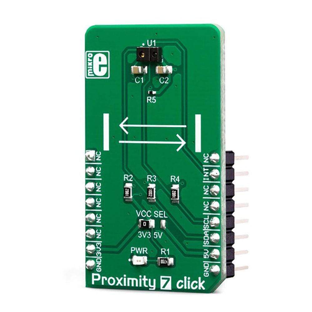
The main component of the Proximity 7 Click Board™ is the ADPS9930, a digital ambient and proximity sensor, by Broadcom (Avago Technologies). It is an accurate and reliable proximity and ambient light sensor, aimed towards power saving in applications that use TFT or LCD panels. By offering a huge dynamic range, the ADPS9930 sensor allows to be placed behind a dark glass or a semi-transparent screen bezel, but also to be exposed to bright sunlight. A proprietary design of the integrated constant-current LED driver enables plug and play proximity detection up to 100mm, eliminating the need for a calibration procedure. By integrating micro-optics elements within the casing, ADPS9930 greatly simplifies the application design.
The proximity of an object is detected using an IR LED, which emits pulses of light towards the object. The amount of the reflected IR light is measured by an integrated IR photodiode on channel 1. During LED ON time, the amount of the reflected IR light is measured and integrated. The background IR light is also measured and integrated, during LED OFF time. It is then subtracted from the final result, allowing for accurate measurement with the reduced amount of the background IR noise. After it has been scaled to a 16-bit value, the final result is available on the output registers, in the LOW/HIGH byte format.
Commonly, photosensitive elements are most sensitive to IR light. A human eye cannot detect IR light. Therefore, the PD element has to filter out IR light so that only the visible part of the light is allowed through. Channel0 is equipped with such PD, making it usable for ALS sensing. During the ALS measurement, both channels are measured. The datasheet of the ADPS9930 offers a conversion formula that can be used to obtain results in physical units (lx). These formulas also take the IR measurement from channel 1 into consideration, completely reducing its influence on the final result. By adjusting the integration time (also known as oversampling), the flickering effect of fluorescent light can be completely eliminated.
The extensive interrupt engine allows an optimized firmware to be written. Four registers are used to specify the low and the high threshold for the ALS and proximity measurements. Whenever these thresholds are exceeded, an interrupt status bit will be set in the respective register. The user has the ability to assign an external pin to an interrupt, so the MCU can be alerted whenever an interrupt event occurs. The interrupt is generated whenever the threshold value is exceeded a programmed number of times (interrupt persistence). This is useful to prevent false and erratic interrupt reporting.
The power consumption is mainly affected by the integration time. It is a mean value of a programmable number of consecutive measurements, which is performed in order to reduce the noise and improve the sensitivity, resolution, etc. However, it has an adverse impact on the overall power consumption, as the time frame during which the device is active, is extended: more measurements, longer activity. The internal state machine puts the ADPS9930 in a standby mode between readings, thus reducing the overall power consumption.
The Proximity 7 Click Board™ uses an I2C interface to communicate with the host MCU. It is equipped with an SMD jumper labelled as VCC SEL. This jumper is used to select the power supply for the pull-up resistors on the I2C bus, allowing both 3.3V and 5V MCUs to be interfaced with this Click board™.
SPECIFICATIONS
| Type | Proximity |
| Applications | It is a perfect choice for a range of applications that rely on proximity and ambient light sensing (ALS), including PC and laptop monitors, POS displays, embedded displays, proximity-activated short-range security, etc. |
| On-board modules | ADPS9930, a digital ambient and proximity sensor, by Broadcom (Avago Technologies). |
| Key Features | A high dynamic range allows using the sensor in both very bright and very dim light conditions. An extensive interrupt engine allows simplified firmware to be written. Low power consumption that can be further tuned according to needs. The proprietary design eliminates the need for calibration. |
| Interface | I2C |
| Compatibility | mikroBUS |
| Click board size | M (42.9 x 25.4 mm) |
| Input Voltage | 3.3V or 5V |
PINOUT DIAGRAM
This table shows how the pinout on the Proximity 7 Click Board™ corresponds to the pinout on the mikroBUS™ socket (the latter shown in the two middle columns).
| Notes | Pin | Pin | Notes | ||||
|---|---|---|---|---|---|---|---|
| NC | 1 | AN | PWM | 16 | NC | ||
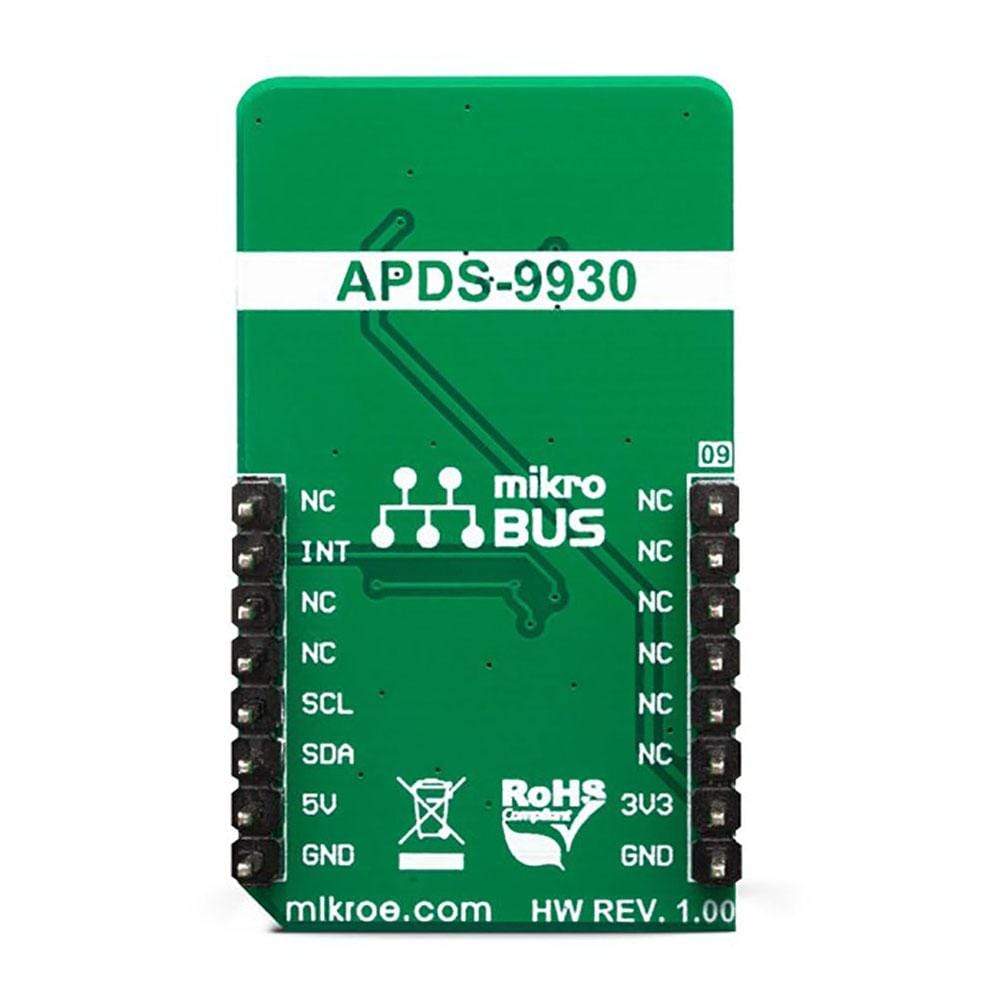
| NC | 2 | RST | INT | 15 | INT | Interrupt output | |
| NC | 3 | CS | RX | 14 | NC | ||
| NC | 4 | SCK | TX | 13 | NC | ||
| NC | 5 | MISO | SCL | 12 | SCL | I2C Clock | |
| NC | 6 | MOSI | SDA | 11 | SDA | I2C Data | |
| Power Supply | 3.3V | 7 | 3.3V | 5V | 10 | 5V | Power Supply |
| Ground | GND | 8 | GND | GND | 9 | GND | Ground |
ONBOARD SETTINGS AND INDICATORS
| Label | Name | Default | Description |
|---|---|---|---|
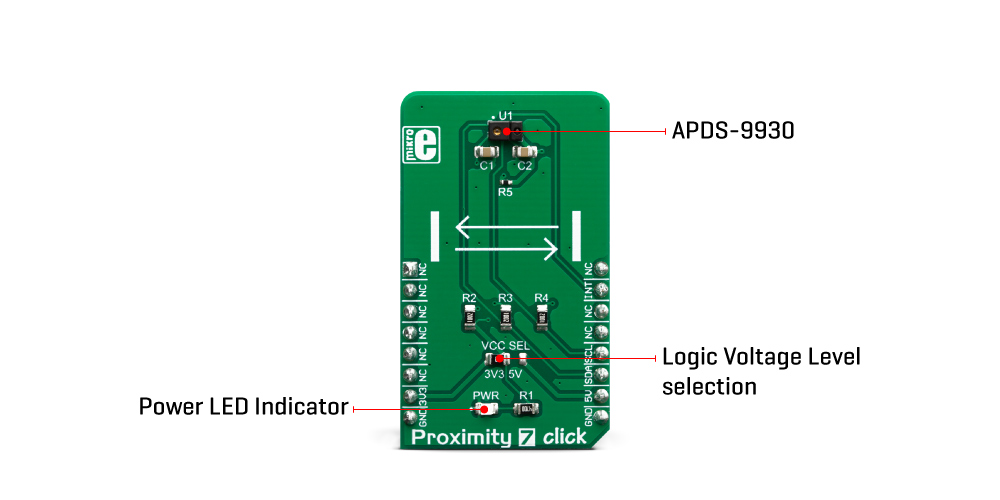
| PWR | PWR | - | Power indication LED |
| VCC SEL | VCC SEL | Left | Logic voltage level selection: left position 3V3, right position 5V |
| General Information | |
|---|---|
Part Number (SKU) |
MIKROE-3330
|
Manufacturer |
|
| Physical and Mechanical | |
Weight |
0.022 kg
|
| Other | |
EAN |
8606018714322
|
Frequently Asked Questions
Have a Question?
Be the first to ask a question about this.