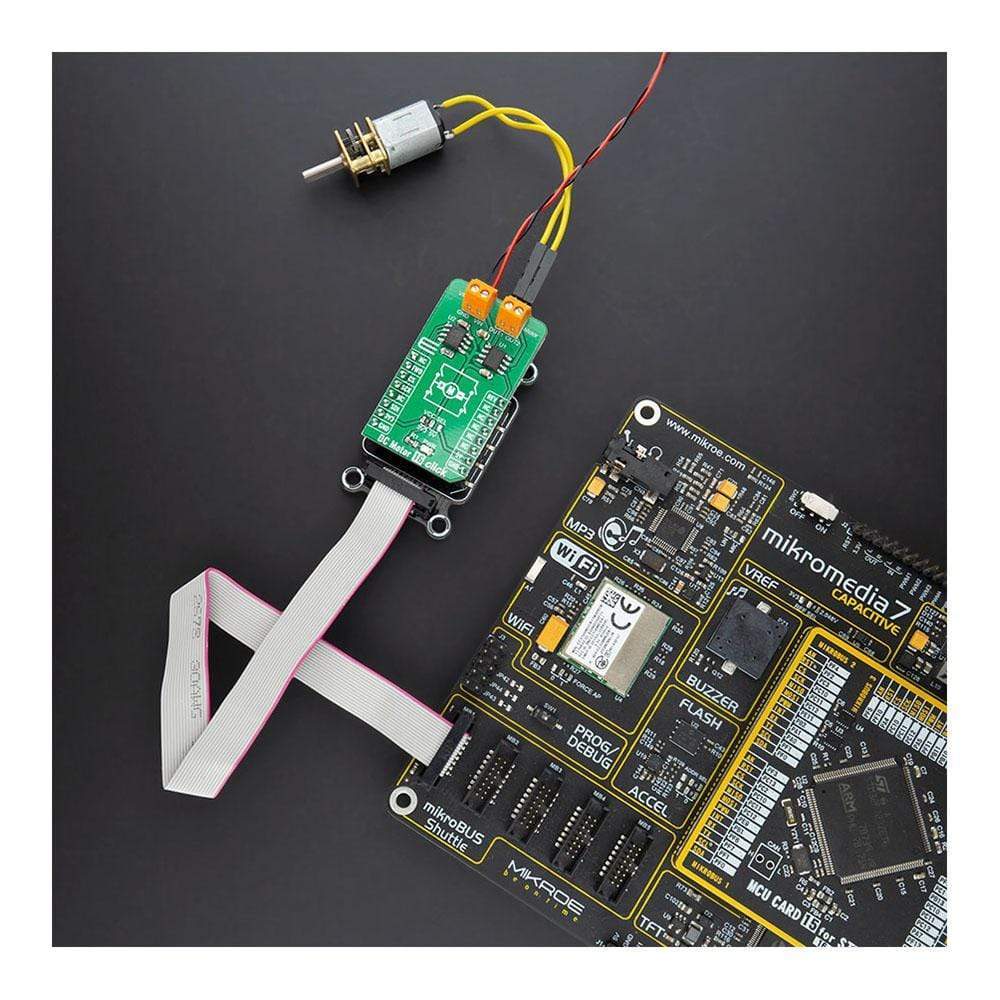
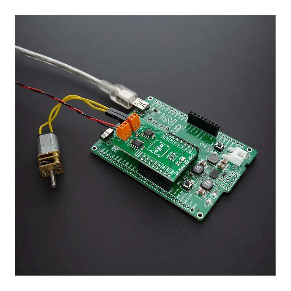
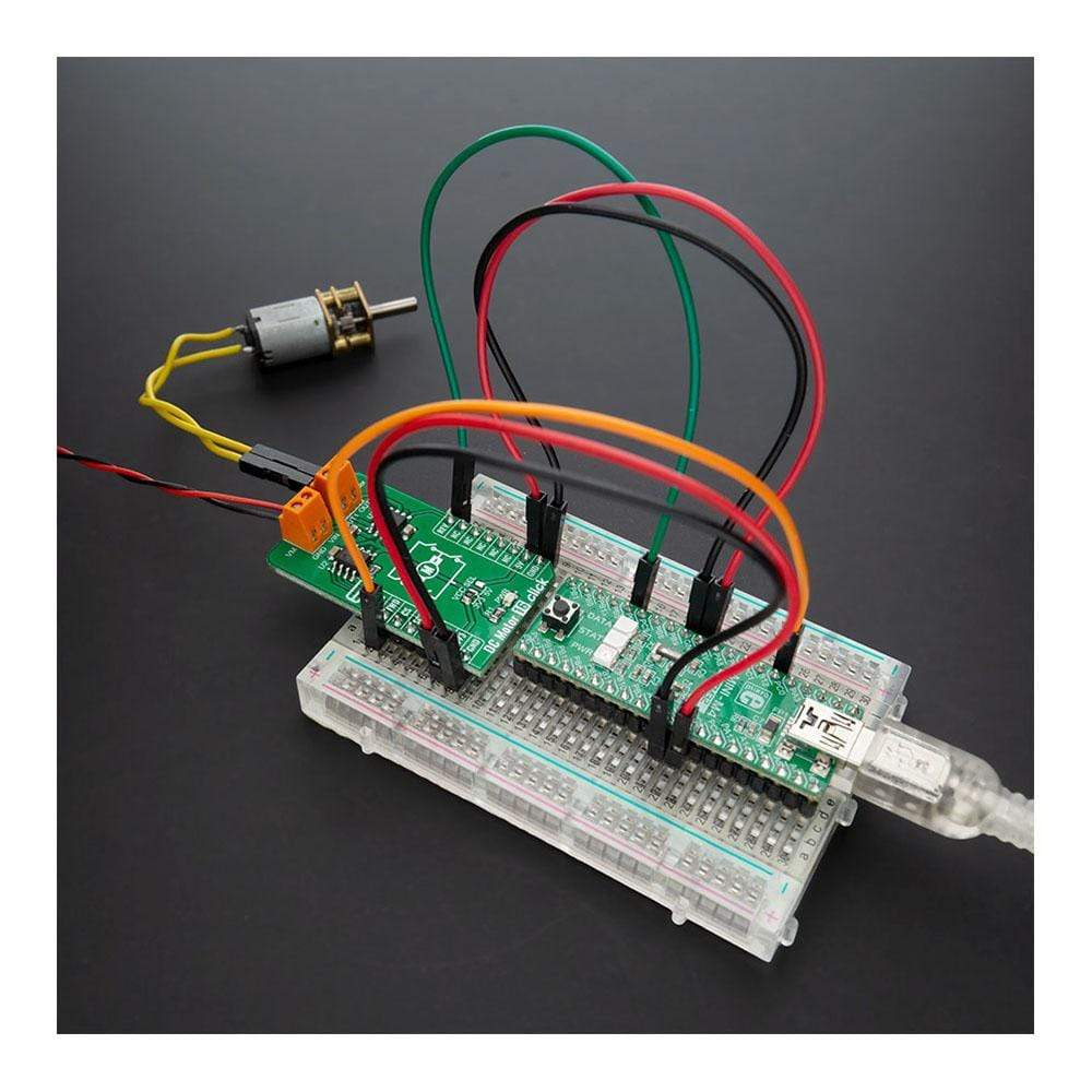
Overview
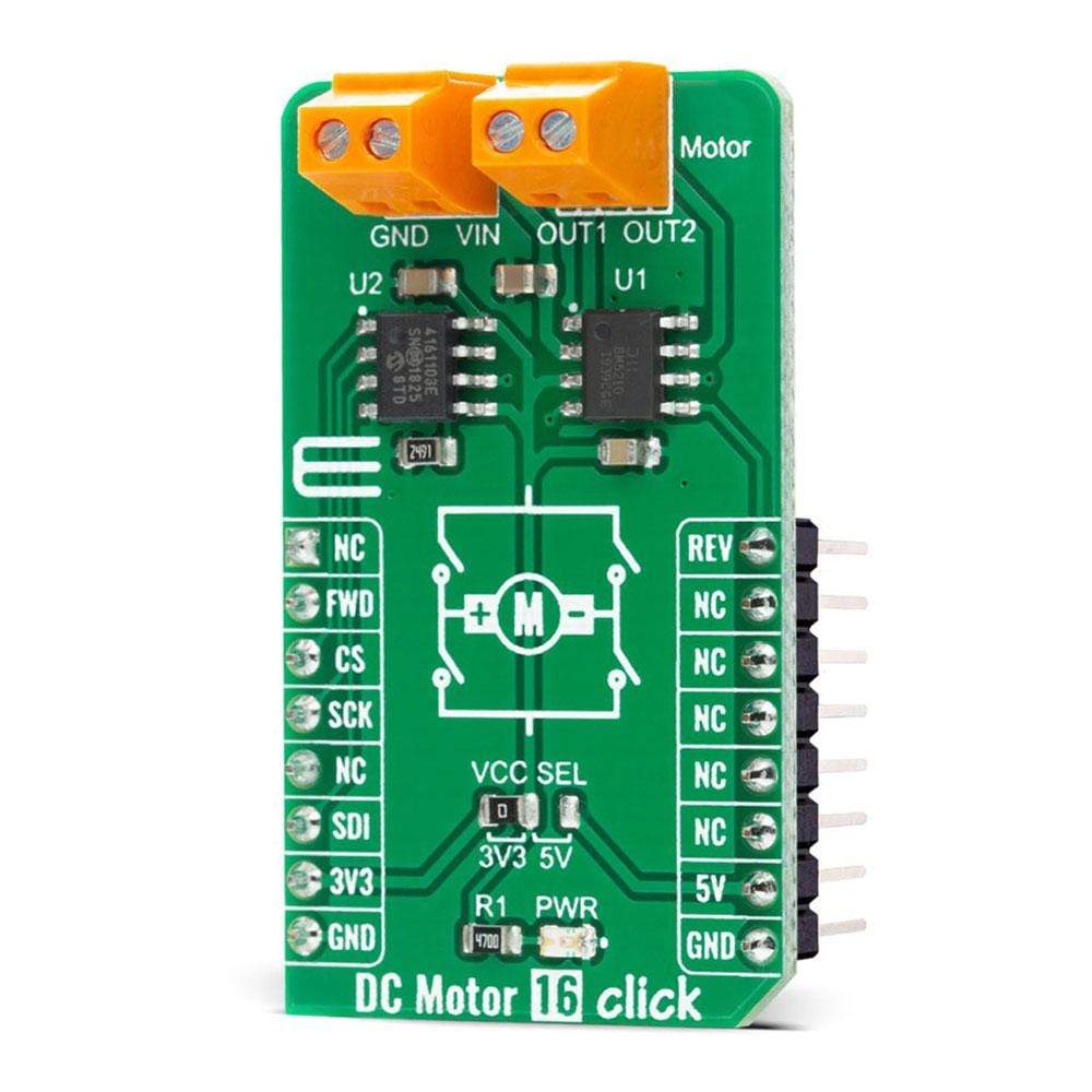
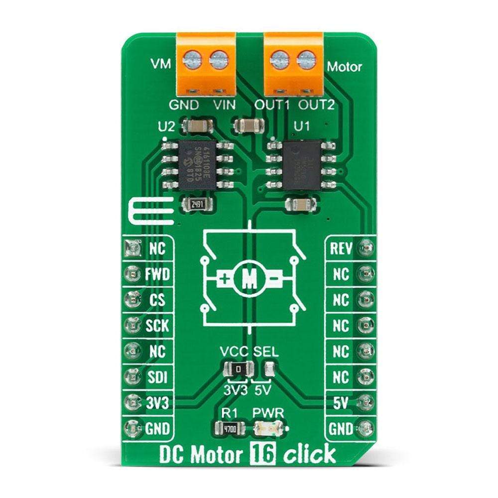
The DC Motor 16 Click Board™ is a compact add-on board that contains a high-performance single phase reversible DC motor drive with speed control. This board features the ZXBM5210, a fully-featured DC motor drive solution with an average current capability of up to 700mA from Diodes Incorporated. The ZXBM5210 has several modes of operations selected by two GPIO pins, has a wide supply voltage range from 3V to 18V, and has low power consumption. It possesses three speed-control modes, and provides under/over voltage protection, over current limit, and thermal shutdown capability. This Click Board™ is suitable for a reversible DC motor and actuator drive, remote control motorized toy applications, home appliances, handheld power tools, and many more.
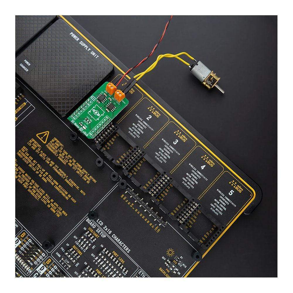
The DC Motor 16 Click Board™ is supported by a mikroSDK compliant library, which includes functions that simplify software development. This Click Board™ comes as a fully tested product, ready to be used on a system equipped with the mikroBUS™ socket.
Downloads
How Does The DC Motor 16 Click Board™ Work?
The DC Motor 16 Click Board™ is based on the ZXBM5210, a single chip solution for driving a single-coil reversible direct current (DC) fans and motors from Diodes Incorporated. The driver output stage is designed to minimize audible switching noise and electromagnetic interference (EMI) ensuring a low noise solution. The device has four motor operation modes:
- Standby
- Forward
- Reverse
- Brake Mode
These four modes are controlled by the FWD and REV pins routed to the RST and PWM pins of the mikroBUS™ used for controlling the motor rotation directions. In the Standby mode, all the internal circuits are turned off to minimize power consumption, while the Brake mode allows the motor to stop quickly. The power consumption in the Standby mode is less than in the Brake mode. To prevent the ZXBM5210 from entering the Standby mode during mode changes, the signal change should be completed within 125μs.
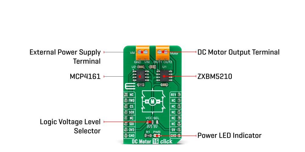
The ZXBM5210 also possesses three modes of motor speed control: VREF speed control mode, PWM speed control mode, and motor speed control by adjusting the supply voltage. Motor speed can be controlled by adjusting the duty cycle of the PWM signal while keeping the supply voltage pin at the nominal motor voltage or can be controlled by varying the supply voltage while the FWD and REV pins are set to either a logic high or low depending on needed motor direction. In PWM Mode the input voltage on the Vref pin of the ZXBM5210 must be greater than or equal to the supply voltage value.
The motor speed of the ZXBM5210 can be controlled by adjusting the DC voltage on the Vref pin. For this purpose, the DC Motor 16 Click Board™ employs the MCP4161 digital potentiometer from Microchip, which allows setting the corresponding voltage value via the SPI serial interface. The potentiometer terminal B is fixed to the Zero-Scale wiper value (which corresponds to a wiper value of 0x00 for both 7-bit and 8-bit devices), while the potentiometer terminal A is fixed connected to the Full-Scale wiper value (which corresponds to a wiper value of 0x100 for 8-bit devices or 0x80 for 7-bit devices). For this reason, it was chosen that when the user selects 0x100 as the desired value, the value on the Vref pin takes the value of supply voltage from the mikroBUS™ (VCC), while in the case of selecting 0x00 on the Vref pin value is equal to the 0.2*VCC. In this mode, FWD and REV pins are only used for direction control, and therefore high-frequency PWM control signal should not be applied to those pins.
The DC Motor 16 Click Board™ is designed to be operated with both 3.3V and 5V logic voltage levels that can be selected via VCC SEL jumper. This allows for both 3.3V and 5V capable MCUs to use the SPI communication lines properly. However, the Click board™ comes equipped with a library that contains easy to use functions and an example code that can be used as a reference for further development.
SPECIFICATIONS
| Type | Brushed |
| Applications | Can be used for a reversible DC motor and actuator drive, remote control motorized toy applications, home appliances, handheld power tools, and many more. |
| On-board modules | The DC Motor 16 Click Board™ is based on the ZXBM5210, a single chip solution for driving a single-coil reversible direct current (DC) fans and motors from Diodes Incorporated. |
| Key Features | Low power consumption, wide supply voltage range, under/over voltage protection, over current limit, thermal shutdown capability, and many more. |
| Interface | GPIO,SPI |
| Compatibility | mikroBUS |
| Click board size | M (42.9 x 25.4 mm) |
| Input Voltage | 3.3V or 5V |
PINOUT DIAGRAM
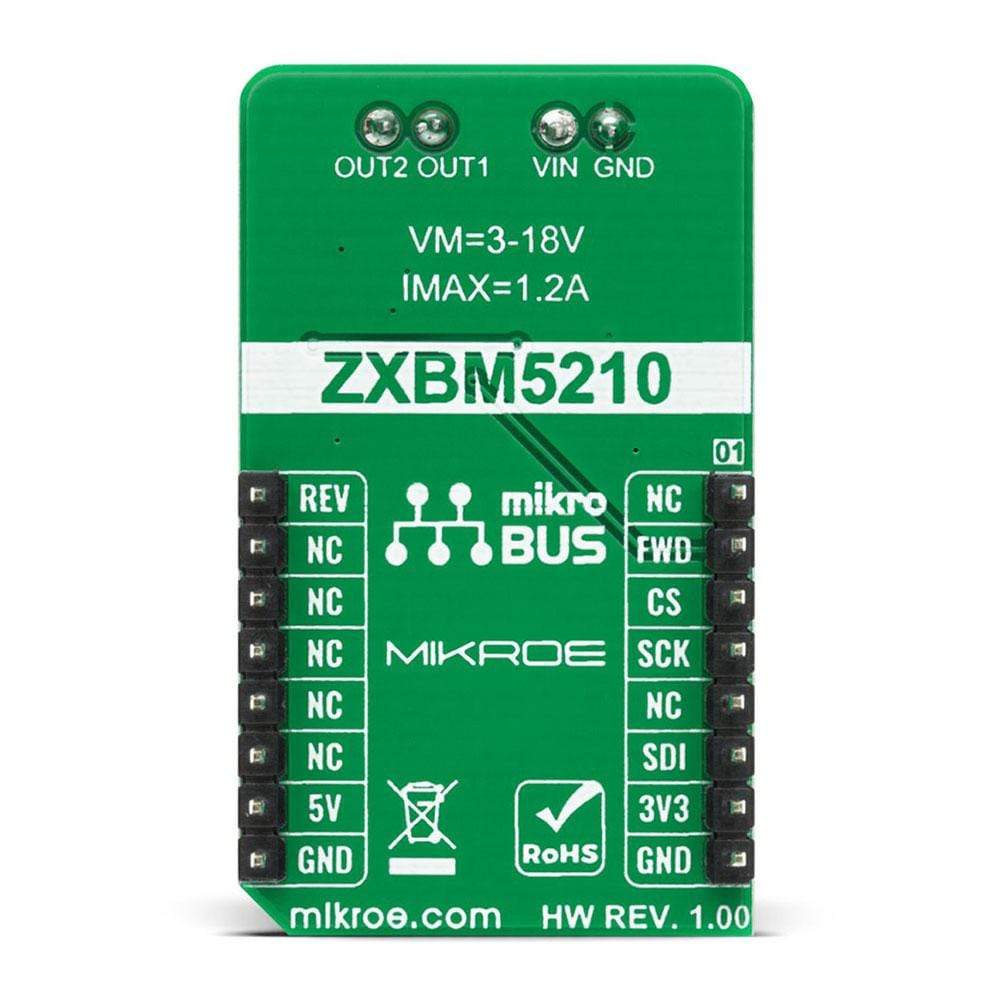
This table shows how the pinout onf the DC Motor 16 Click Board™ corresponds to the pinout on the mikroBUS™ socket (the latter shown in the two middle columns).
| Notes | Pin |  |
Pin | Notes | |||
|---|---|---|---|---|---|---|---|
| NC | 1 | AN | PWM | 16 | REV | Reverse Direction PWM Control Signal |
|
| Forward Direction | FWD | 2 | RST | INT | 15 | NC | |
| SPI Chip Select | CS | 3 | CS | RX | 14 | NC | |
| SPI Clock | SCK | 4 | SCK | TX | 13 | NC | |
| NC | 5 | MISO | SCL | 12 | NC | ||
| SPI Data IN | SDI | 6 | MOSI | SDA | 11 | NC | |
| Power Supply | 3.3V | 7 | 3.3V | 5V | 10 | 5V | Power Supply |
| Ground | GND | 8 | GND | GND | 9 | GND | Ground |
ONBOARD SETTINGS AND INDICATORS
| Label | Name | Default | Description |
|---|---|---|---|
| LD1 | PWR | - | Power LED Indicator |
| JP1 | VCC SEL | Left | Power Supply Voltage Selection 3V3/5V: Left position 3V3, Right position 5V |
DC MOTOR 16 CLICK ELECTRICAL SPECIFICATIONS
| Description | Min | Typ | Max | Unit |
|---|---|---|---|---|
| External Supply Voltage | 3 | - | 18 | V |
| FWD and REV Pin Voltage | -0.3 | - | 7 | V |
| Maximum Output Current | - | 700 | 1200 | mA |
| PWM Speed Control Signal Frequency | 8 | 25 | 100 | kHz |
| Operating Temperature Range | -40 | - | +85 | °C |
| General Information | |
|---|---|
Part Number (SKU) |
MIKROE-4333
|
Manufacturer |
|
| Physical and Mechanical | |
Weight |
0.02 kg
|
| Other | |
Country of Origin |
|
HS Code Customs Tariff code
|
|
EAN |
8606027380716
|
Warranty |
|
Frequently Asked Questions
Have a Question?
Be the first to ask a question about this.


