


Mikroelektronika d.o.o.
Thermostat 4 Click Board™
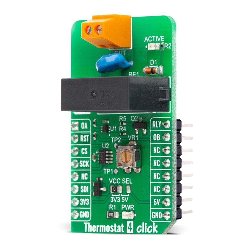
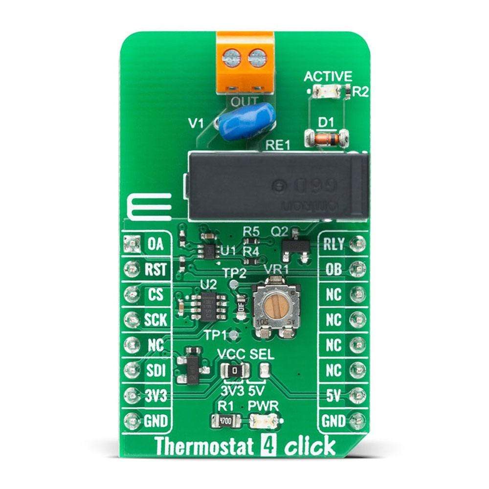
Thermostat 4 Click Board™
SKU: MIKROE-4194
Couldn't load pickup availability
Overview
The Thermostat 4 Click Board™ is a complete solution that senses the temperature of a physical system and can perform actions so that the system's temperature is maintained near a desired setpoint. It's based on Texas Instruments TMP392, a resistor programmable temperature switch that enables protection and detection of system thermal events from 30°C to 130°C. It offers dual overtemperature (hot and warm) detection. The trip temperatures option is programmed by changing the trimmer resistance value for channel A and digital potentiometer resistance value over the SPI interface for channel B. The Thermostat 4 Click also contains a high-quality relay from Omron, that can be used to open or close an electric circuit. Despite its small size, it can be used with voltage up to 30VDC/220AC and current up to 5A.
The Thermostat 4 Click Board™ is supported by a mikroSDK compliant library, which includes functions that simplify software development. This Click Board™ comes as a fully tested product, ready to be used on a system equipped with the mikroBUS™ socket.
Downloads
How Does The Thermostat 4 Click Board™ Work?
The Thermostat 4 Click Board™ uses the output of the TMP392 as open-drain and with two 10k pull-up resistors on mikroBUS™ OA and OB pins connected to VCC voltage indicate when a threshold temperature is detected. The device powers on when the supply voltage goes beyond 1.5V, and starts sampling the input resistance to set the two trip points and hysteresis value after power-on. Resistance values for each temperature can be find in TMP392 datasheet Table 1 and Table 2. These values will remain the same until the device goes through a power cycle.
.jpg)
Trip point for channel A can be set manually using onboard trimmer while trip point for channel B is set using TPL0501 digital potentiometer with 256 wiper positions used as as a two-terminal rheostat. With end-to-end resistance of 100 kΩ internal registers of the TPL0501 can be accessed using a SPI interface. The position of the wiper (W) terminal is controlled by the value in the 8-bit Wiper Resistance (WR) register. When the WR register contains all zeroes (zero-scale), the wiper terminal is closest to its L terminal. As the value of the WR register increases from all zeroes to all ones (full-scale), the wiper moves from the position closest to the L terminal, to the position closest to the H terminal. At the same time, the resistance between W and L increases, whereas the resistance between W and H decreases.
The relay is activated by the host MCU. The voltage for the coil activation is 5V, while the current through the coil is 40mA. The MCU is not able to drive the coil directly, therefore an N-chanel FET had to be added. Its gate is controlled by the host MCU, allowing the coil to drain enough current from the 5V mikroBUS™ power rail. A red color LED, labelled as ACTIVE is used to indicate that the transistor is in an open state and that the current is running through the relay coil.
When the current through a coil (or any other inductor) is suddenly changed, the backEMF will be generated, opposing the changes of the current. This can sometimes lead to damage to the control circuit: in this case, the transistor will become inversely polarized. To prevent this from happening, a flyback diode is added across the coil. During the normal operation, this diode does not conduct any current. However, when the coil is switched OFF, the inverse polarization will cause the current to pass through this diode with minimum resistance. This prevents inverse (flyback) voltage from building up, so the transistor remains safe.
The Thermostat 4 Click Board™ is equipped with all the necessary elements, required to provide a reliable operation: it has a varistor across the relay output contacts, preventing excessive voltage transients, it has a flyback diode for the backEMF generated within the relay coil, and a durable mechanical relay, that can withstand up to 20,000,000 mechanical cycles (no load connected). These features allow Thermostat 4 Click Board™ to be used for a wide range of applications that have to be thermally controlled: various home appliances, air conditioners, cooling fans, small heaters, etc.
SPECIFICATIONS
| Type | Temperature & humidity |
| Applications | The Thermostat 4 Click Board™ can be used for a wide range of applications that have to be thermally controlled: various home appliances, air conditioners, cooling fans, small heaters, etc |
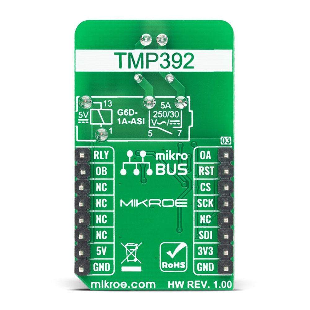
| On-board modules | TMP392 |
| Key Features | Dual outputs for overtemperature detection, Trip test function enables in-system testing, Resistor tolerances contribute zero error |
| Interface | GPIO,SPI |
| Compatibility | mikroBUS |
| Click board size | M (42.9 x 25.4 mm) |
| Input Voltage | 3.3V or 5V |
PINOUT DIAGRAM
This table shows how the pinout of the Thermostat 4 Click Board™ corresponds to the pinout on the mikroBUS™ socket (the latter shown in the two middle columns).
| Notes | Pin | Pin | Notes | ||||
|---|---|---|---|---|---|---|---|
| Channel A Output | OA | 1 | AN | PWM | 16 | RLY | Relay Control |
| Reset | RST | 2 | RST | INT | 15 | OB | Channel B Output |
| SPI Chip Select | CS | 3 | CS | RX | 14 | NC | |
| SPI Clock | SCK | 4 | SCK | TX | 13 | NC | |
| NC | 5 | MISO | SCL | 12 | NC | ||
| SPI Data IN | SDI | 6 | MOSI | SDA | 11 | NC | |
| Power Supply | 3.3V | 7 | 3.3V | 5V | 10 | 5V | Power Supply |
| Ground | GND | 8 | GND | GND | 9 | GND | Ground |
ONBOARD SETTINGS AND INDICATORS
| Label | Name | Default | Description |
|---|---|---|---|
| PWR | LD1 | - | Power LED Indicator |
| ACTIVE | LD2 | - | Relay active LED indicator |
| VCC SEL | JP1 | Left | Logic level voltage selection: left position 3V3, right position 5V |
| General Information | |
|---|---|
Part Number (SKU) |
MIKROE-4194
|
Manufacturer |
|
| Physical and Mechanical | |
Weight |
0.022 kg
|
| Other | |
EAN |
8606027380051
|
Frequently Asked Questions
Have a Question?
Be the first to ask a question about this.