


Mikroelektronika d.o.o.
MUX 3 Click Board™
MUX 3 Click Board™
SKU: MIKROE-3916
Couldn't load pickup availability


Overview
The MUX 3 Click Board™ is the general purpose multiplexer which offers multiplexing one input channel to eight single-ended output channels. Given the TMUX1208 wide operating supply options from 1.08 V to 5.5 V and support of bidirectional I/O signals, its allowing you use in a broad array of applications ranging from personal electronics to building automation applications such as: Heating, Smoke Detectors, Ventilation, Air Conditioning, Battery-Powered Equipment, Consumer Audio, etc.
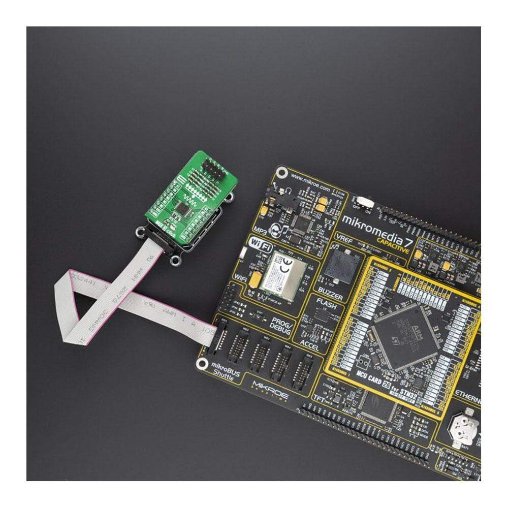
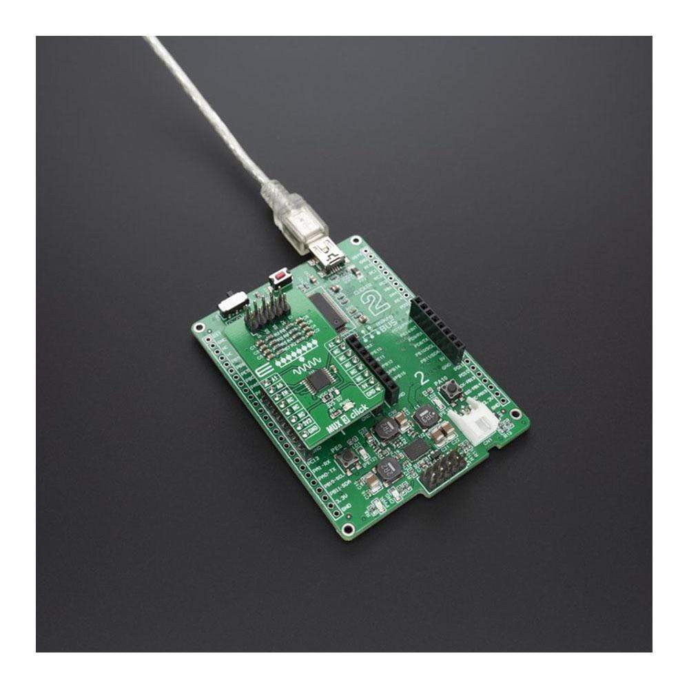
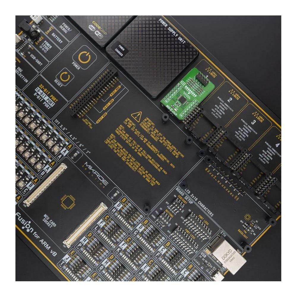
The MUX 3 Click Board™ is supported by a mikroSDK compliant library, which includes functions that simplify software development. This Click Board™ comes as a fully tested product, ready to be used on a system equipped with the mikroBUS™ socket.
Downloads
How Does The MUX 3 Click Board™ Work?
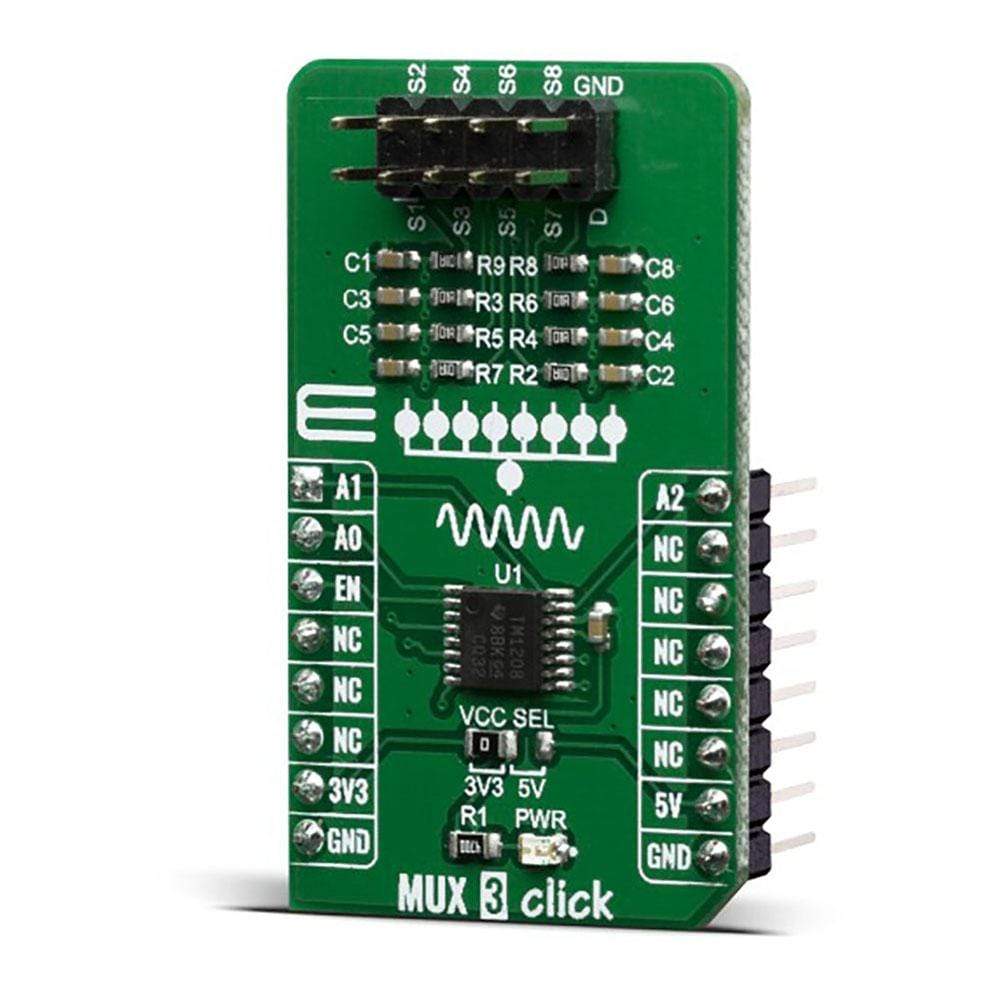
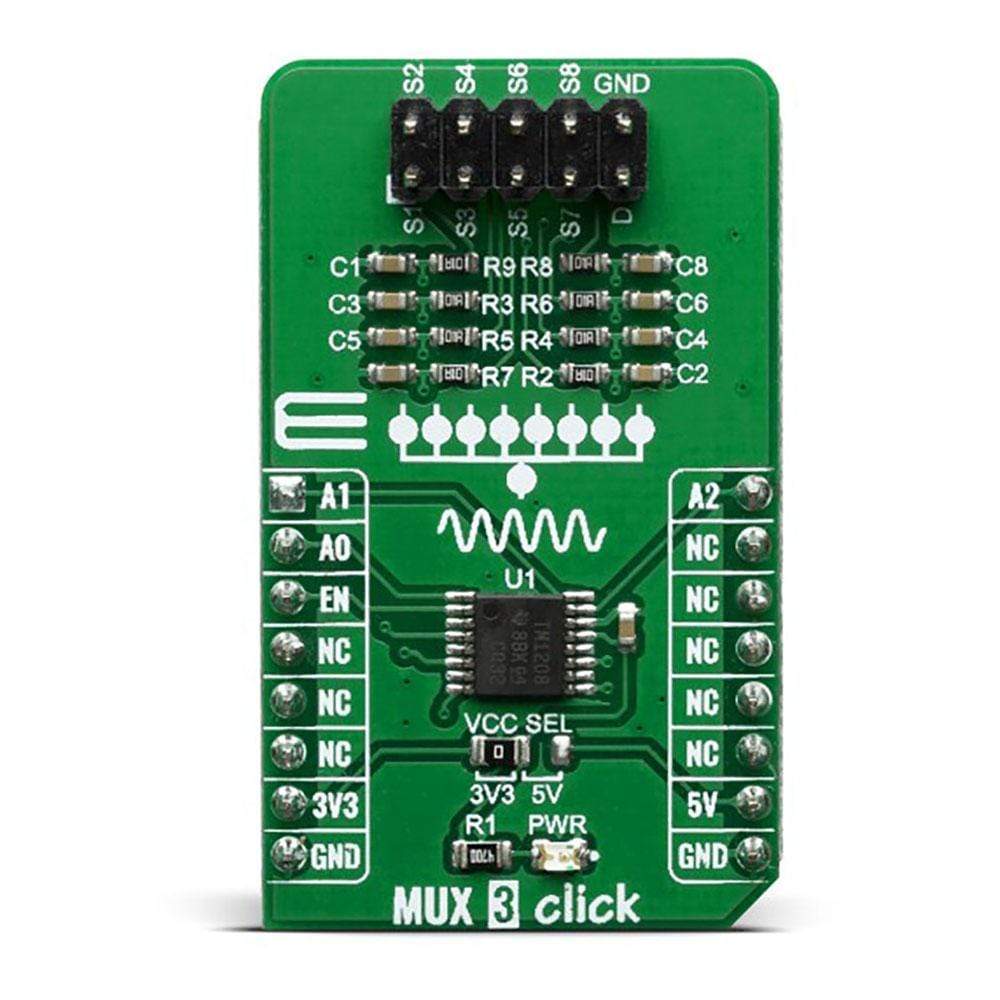
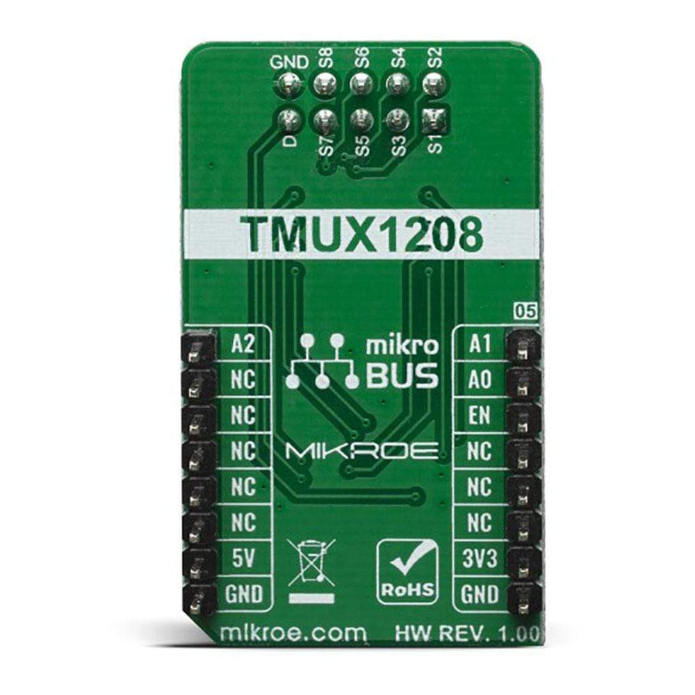
The MUX 3 Click Board™ is based around the TMUX1208 module, a 5-V Bidirectional 8:1, 1-Channel Multiplexer from Texas Instruments. The TMUX1208 is a general purpose complementary metal-oxide semiconductor (CMOS) multiplexer (MUX). Wide operating supply of 1.08 V to 5.5 V allows for use in a broad array of applications from personal electronics to building automation applications.
The device supports bidirectional analog and digital signals on the source (Sx) and drain (D) pins ranging from GND to VDD. All logic inputs have 1.8 V logic compatible thresholds, ensuring both TTL and CMOS logic compatibility when operating in the valid supply voltage range. Fail-Safe Logic circuitry allows voltages on the control pins to be applied before the supply pin, protecting the device from potential damage.
Break-before-make delay is a safety feature that prevents two inputs from connecting when the device is switching. The output first breaks from the on-state switch before making the connection with the next on-state switch. The time delay between the break and the make is known as break-before-make delay.
One useful application to take advantage of the TMUX1208 features is multiplexing various signals into an ADC that is integrated into a MCU. Utilizing an integrated ADC in a MCU allows a system to minimize cost with a potential tradeoff of system performance when compared to an external ADC. The multiplexer allows for multiple inputs/sensors to be monitored with a single ADC pin of the device, which is critical in systems with limited I/O.
Given all the features the TMUX1208 offers, the MUX 3 Click Board™ is best used for Analog and Digital Multiplexing / Demultiplexing, HVAC: Heating, Ventilation, and Air Conditioning, Smoke Detectors, Video Surveillance, Electronic Point of Sale, Battery-Powered Equipment, Appliances, and Consumer Audio.
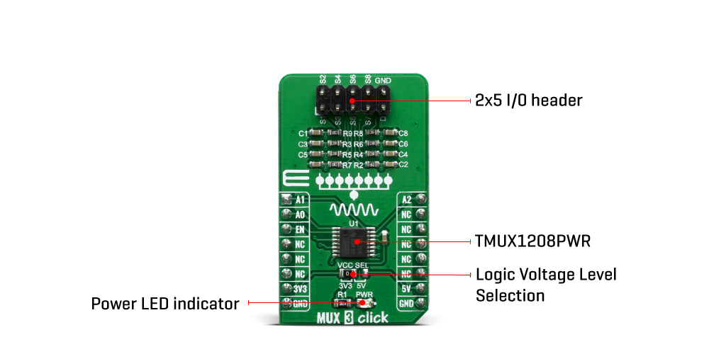
The MUX 3 Click Board™ offers a selection between 3.3V and 5V operation, with the onboard SMD jumper, labelled as VCC SEL. This allows both 3.3V and 5V MCUs to be interfaced with this Click board™.
SPECIFICATIONS
| Type | DAC |
| Applications | Analog and Digital Multiplexing / Demultiplexing, HVAC: Heating, Ventilation, and Air Conditioning, Smoke Detectors, Video Surveillance, Electronic Point of Sale, Battery-Powered Equipment, Appliances, Consumer Audio |
| On-board modules | TMUX1208, a 5-V Bidirectional 8:1, 1-Channel Multiplexer from Texas Instruments |
| Key Features | Features such as the break-before-make switching action, electrostatic discharge protection up to 2kV, low on-resistance and low input current leakage, make this circuit a perfect solution for various switching applications, especially those that utilize differential signals |
| Interface | GPIO |
| Compatibility | mikroBUS |
| Click board size | M (42.9 x 25.4 mm) |
| Input Voltage | 3.3V or 5V |
PINOUT DIAGRAM
This table shows how the pinout of the MUX 3 Click Board™ corresponds to the pinout on the mikroBUS™ socket (the latter shown in the two middle columns).
| Notes | Pin | Pin | Notes | ||||
|---|---|---|---|---|---|---|---|
| Control pin 1 | A1 | 1 | AN | PWM | 16 | A2 | Control pin 2 |
| Control pin 0 | A0 | 2 | RST | INT | 15 | NC | |
| Enable Chip | EN | 3 | CS | RX | 14 | NC | |
| NC | 4 | SCK | TX | 13 | NC | ||
| NC | 5 | MISO | SCL | 12 | NC | ||
| NC | 6 | MOSI | SDA | 11 | NC | ||
| Power Supply | 3.3V | 7 | 3.3V | 5V | 10 | 5V | Power Supply |
| Ground | GND | 8 | GND | GND | 9 | GND | Ground |
ONBOARD SETTINGS AND INDICATORS
| Label | Name | Default | Description |
|---|---|---|---|
| LD1 | PWR | - | Power LED Indicator |
| JP1 | VCC SEL | Left | Power supply voltage selection: left position 3.3V, right position 5V |
| General Information | |
|---|---|
Part Number (SKU) |
MIKROE-3916
|
Manufacturer |
|
| Physical and Mechanical | |
Weight |
0.018 kg
|
| Other | |
EAN |
8606018719075
|
Frequently Asked Questions
Have a Question?
Be the first to ask a question about this.