
Overview
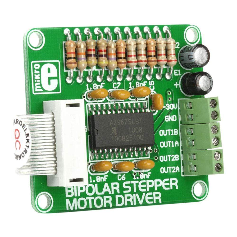
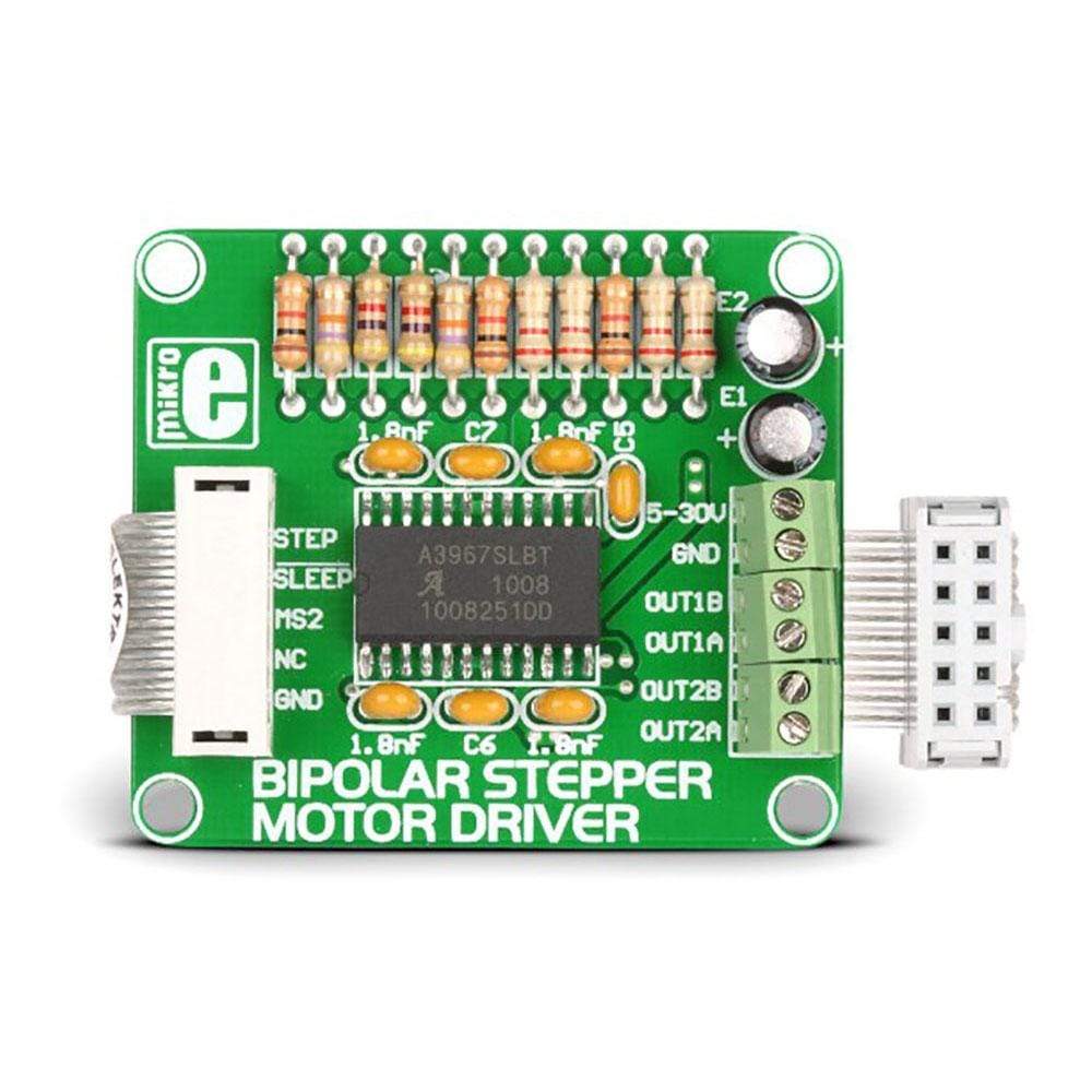
The Bipolar Stepper Motor Driver Board comes designed to let the user operate bipolar stepper motors in full-, half-, quarter-and eight-step modes. This additional board comes equipped with a complete microstepping motor driver with an in-built A3967SLB translator. The accessory board also includes a fixed off-time current regulator, which is capable of operating in slow, fast, or mixed current-decay mode. This current-decay control scheme not only increases step accuracy but also results in less power consumption and much reduced audible motor noise.
The Bipolar Stepper Motor Driver Board, which is available as a stand-alone device, can also be connected to the microcontroller. For establishing the connection of the Bipolar Stepper Motor Driver to the microcontroller on the development system, the user needs to use a flat cable with a regular IDC female connector. This female connector in turn should be connected to some development system.
Downloads
A3967SLB built-in translator circuit
The Bipolar Stepper Motor Driver Board operates with help of an integrated A3967SLB circuit. This circuit features thermal shutdown with hysteresis, crossover-current protection and under-voltage lockout, and its operation mode depends on the logic state of seven input pins. This translator equips driving step motors with output driver capability of up to 30V and current up to 750mA.
Board Connection
The Bipolar Stepper Motor Driver Board is clearly marked, which makes it easier to connect with external electronics.Bipolar stepper motors stator features two independent coils (A and B). The ending terminals of these coils need to be connected to the CN3 and CN4 connectors (OUT1A, OUT1B, OUT2A and OUT2B pins). Voltage used for driving these coils is supplied on the CN2 connector.
Resolution
With help of this Bipolar Stepper Motor Driver Board, you would be able to drive the motor in different step modes. The size of one increment (resolution) is equal to a movement of rotor generated by one pulse on step input. The resolution is determined by logic state on MSi and MS2 inputs.
| General Information | |
|---|---|
Part Number (SKU) |
MIKROE-334
|
Manufacturer |
|
| Physical and Mechanical | |
Weight |
0.015 kg
|
| Other | |
Warranty |
|
HS Code Customs Tariff code
|
|
EAN |
8606015070407
|
Frequently Asked Questions
Have a Question?
Be the first to ask a question about this.


