Overview
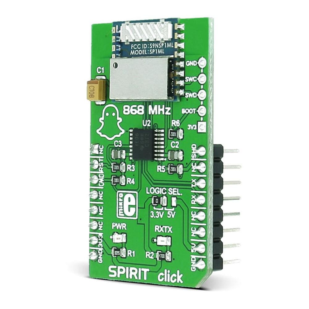
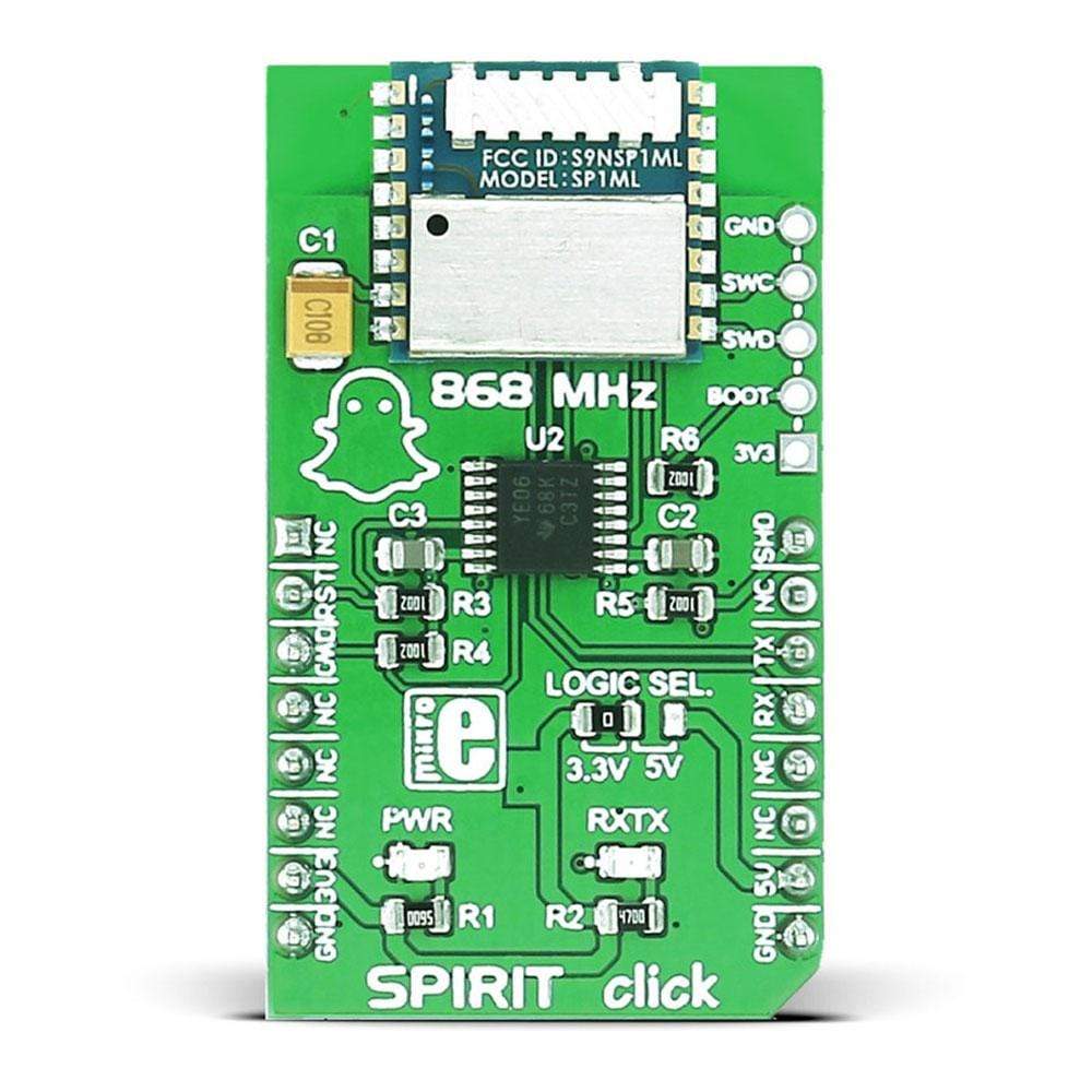
The Spirit Click Board™ carries the SP1ML 868MHz ultra-low-power RF module. The board is designed to use a 3.3V power supply and 3.3V or 5V I/O voltage levels. It communicates with the target MCU over the UART interface, with additional functionality provided by the following pins on the MikroBUS line: PWM, RST, CS.
It can be used to wirelessly send and receive UART data.
Downloads
The SPIRIT Click Board™ carries the SP1ML 868MHz ultra low-power RF module. The board is designed to use 3.3V power supply and 3.3V or 5V I/O voltage levels. It communicates with the target MCU over UART interface, with additional functionality provided by the following pins on the mikroBUS™ line: PWM, RST, CS.
It can be used to wirelessly send and receive UART data.
SP1ML 868MHZ RF MODULE FEATURES
SP1ML is based on the SPIRIT1 RF sub-GHz transceiver (with integrated SMPS), STM32L1 microcontroller, integrated filter/balun, and chip antenna.
There are two operational modes, command mode and operating mode. The command mode allows module configuration and status interrogation using an extended 'AT' style command set. In operating mode the module serves its primary purpose as a wireless transceiver.
In operating mode the module uses only 13.5mA, 2.2mA in command mode, and even lower in standby with just 1.4µA. This kind of power consumption makes it ideal for smart devices that send small amounts of data.
The module has an integrated antenna and crystal.
SPECIFICATIONS
| Type | Sub-1 GHz Transceivers |
| Applications | Security systems, mobile health and medicine applications, IoT, wireless metering, etc. |
| On-board modules | SP1ML 868MHz ultra low-power RF module |
| Radio Region | Europe |
| Key Features | Low data rate, low power sub-GHz transceiver |
| Interface | GPIO,UART |
| Compatibility | mikroBUS |
| Click board size | M (42.9 x 25.4 mm) |
| Input Voltage | 3.3V or 5V |
PINOUT DIAGRAM
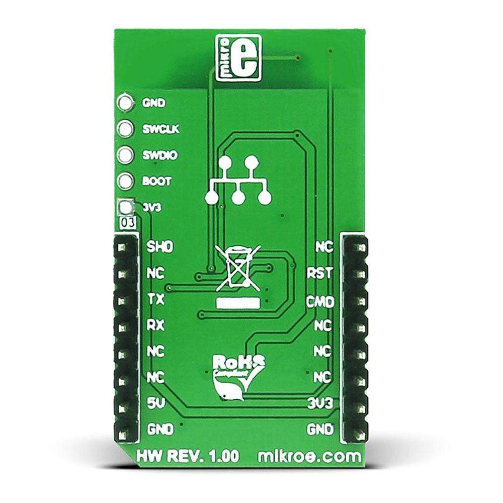
This table shows how the pinout of SPIRIT Click Board™ corresponds to the pinout on the mikroBUS™ socket (the latter shown in the two middle columns).
| Notes | Pin |  |
Pin | Notes | |||
|---|---|---|---|---|---|---|---|
| NC | 1 | AN | PWM | 16 | SHDN | Shutdown | |
| Reset input, active low | RST | 2 | RST | INT | 15 | NC | |
| Command mode | CMD | 3 | CS | TX | 14 | TXD | UART transmit data |
| NC | 4 | SCK | RX | 13 | RXD | UART receive data | |
| NC | 5 | MISO | SCL | 12 | NC | ||
| NC | 6 | MOSI | SDA | 11 | NC | ||
| Power supply | +3.3V | 7 | 3.3V | 5V | 10 | +5V | Power supply |
| Ground | GND | 8 | GND | GND | 9 | GND | Ground |
JUMPERS AND SETTINGS
LOGIC SEL - used to select 3.3 or 5V logical level for UART communication (J1A in the schematic).
| General Information | |
|---|---|
Part Number (SKU) |
MIKROE-2568
|
Manufacturer |
|
| Physical and Mechanical | |
Weight |
0.02 kg
|
| Other | |
Country of Origin |
|
HS Code Customs Tariff code
|
|
EAN |
8606018710287
|
Warranty |
|
Frequently Asked Questions
Have a Question?
Be the first to ask a question about this.

