


Mikroelektronika d.o.o.
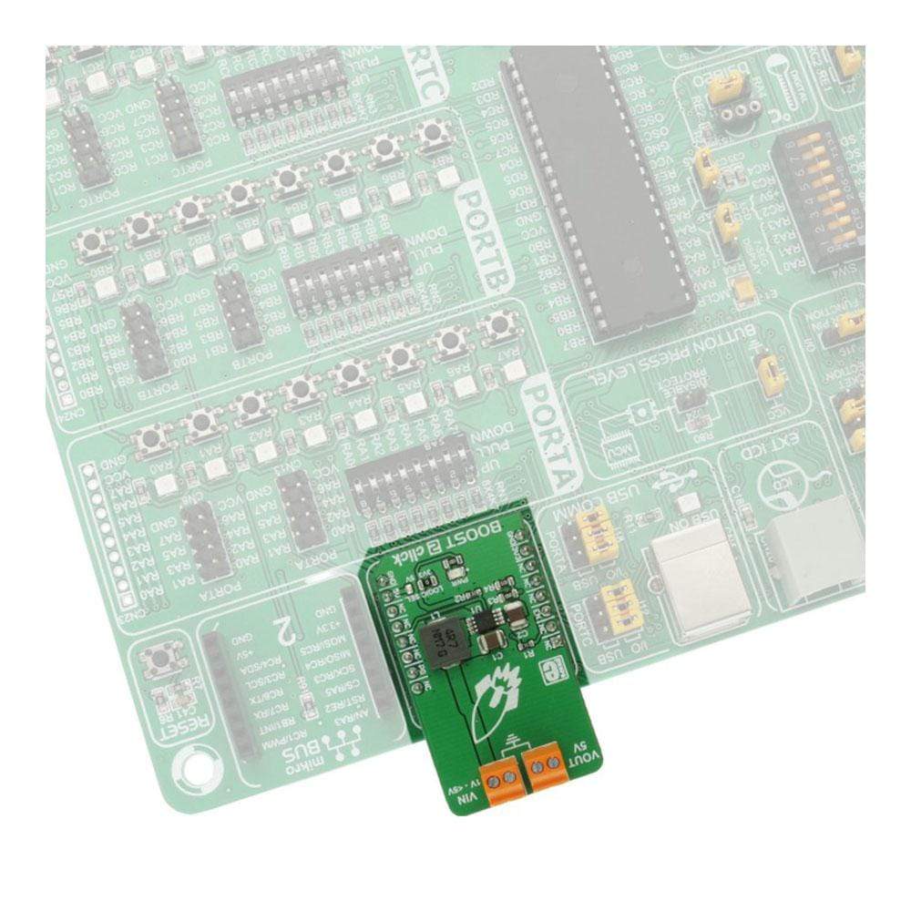
Boost 2 Click Board™
Boost 2 Click Board™
SKU: MIKROE-2894
Couldn't load pickup availability

Overview
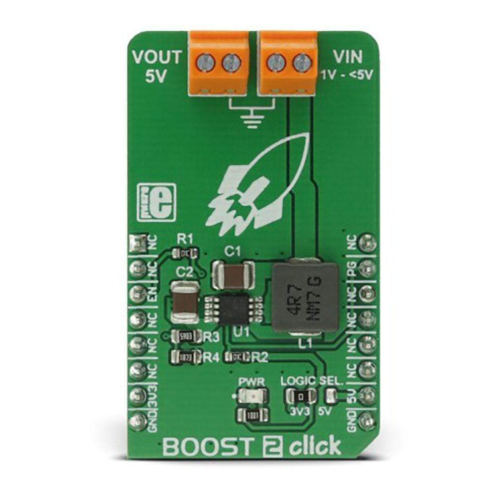
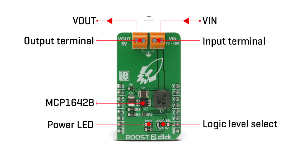
The Boost 2 Click Board™ is a DC-DC step-up (boost) regulator that has a fixed 5V output, which can be obtained from any low voltage input - such as NiCd, NiMH or one cell Li-Po/Li-Ion batteries. The Boost 2 Click Board™ features very high efficiency, low noise and anti-ringing voltage output and inrush current limiting with the internal soft-start, as well as a true disconnect option for minimized power drain, when in shutdown mode.
Downloads
The Boost 2 Click Board™ is a DC-DC step-up (boost) regulator that has a fixed 5V output, which can be obtained from any low voltage input - such as NiCd, NiMH or one cell Li-Po/Li-Ion batteries. This click features very high efficiency, low noise and anti-ringing voltage output and inrush current limiting with the internal soft-start, as well as true disconnect option for minimized power drain, when in shutdown mode.
These features allow this device to be used as the power source for various battery-operated devices, especially for those which require 5V, such as the PIC® family of microcontrollers, various portable embedded electronic devices, handheld instruments, GPS modules, or various battery-operated USB emergency backup chargers. Very good switching efficiency factor ensures prolonged battery life for any application this device is used in.
How Does The Boost 2 Click Board™Work?
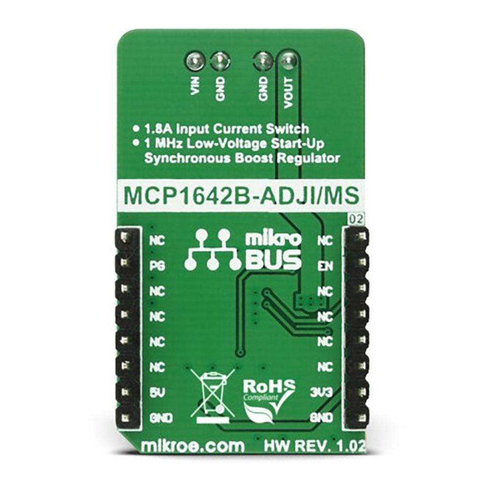
The Boost 2 Click Board™ utilizes the MCP1642B, a 1 MHz low-voltage start-up synchronous boost regulator from Microchip. This IC is targeted towards boosting the voltage from NiCd, NiMH, Li-Po/Li-Ion batteries and as such it has a great efficiency factor, that allows for prolonged battery life. The MCP1642B-ADJ IC uses the fixed switching frequency of 1MHz and has the overcurrent and overtemperature protection to ensure safe operation.
The voltage step-up process starts with the input voltage as low as 0.9V. Once the regulation is established, the input voltage is allowed to drop down to even 0.5V keeping the required regulated voltage at the output. For the optimal efficiency, the device should be powered with at least 1.8V at the input terminal. Output current depends on the input voltage - when powered with 3.3V at the input, BOOST 2 click will be able to deliver about 800mA to the connected load. The device does not have any under-voltage protection limit, so it will start the voltage boosting as soon as the input voltage reaches 0.9V. As with the most step-up regulators, the input voltage should always be less than the voltage at the output to maintain the proper regulation.
The MCP1642B-ADJ step-up regulator actively damps the oscillations typically found at the switch node of a boost converter. This removes the high-frequency radiated noise, ensuring low noise operation.
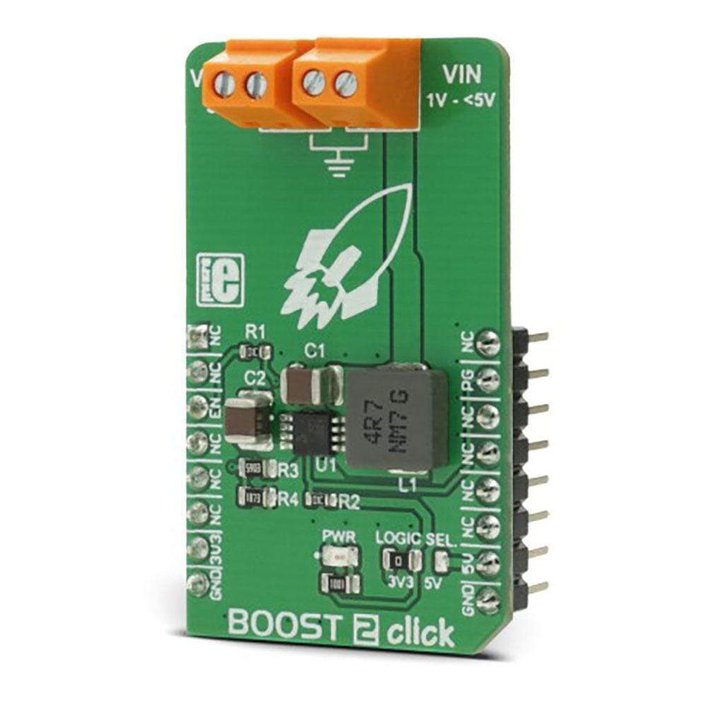
The device also features the power good status pin, which is constructed as the open-drain output, that is pulled HIGH by the onboard 10K resistor. This allows an easy interfacing with the MCU. When the regulated output reaches 90% of its regulation, this pin will be pulled low, indicating the power good status. This pin is routed to the mikroBUS™ INT pin.
Besides the power good status pin, the EN pin used to enable the device is routed to the mikroBUS™ CS pin. When pulled LOW, this pin will engage the true disconnect of the output load option, resulting in very low quintessential currents, suitable for the battery-operated devices. This pin is also pulled HIGH by the onboard resistor.
An onboard SMD jumper, labeled as LOGIC SEL is used to set the voltage levels for the EN and PG pins of the MCP1642B-ADJ. It allows for both 3.3V and 5V MCUs to be interfaced with the Boost 2 Click Board™.
SPECIFICATIONS
| Type | Boost |
| Applications | For various battery-operated devices, especially for those which require 5V, such as the PIC® family of microcontrollers, various portable embedded electronic devices, handheld instruments, GPS modules, etc. |
| On-board modules | MCP1642B-ADJ, a 1 MHz low-voltage start-up synchronous boost regulator from Microchip |
| Key Features | Good efficiency suitable for battery powered devices, low noise, low voltage start up, soft start and true disconnect option. |
| Interface | GPIO |
| Compatibility | mikroBUS |
| Click board size | M (42.9 x 25.4 mm) |
| Input Voltage | 3.3V or 5V |
Pinout Diagram
This table shows how the pinout of the Boost 2 Click Board™ corresponds to the pinout on the mikroBUS™ socket (the latter shown in the two middle columns).
| Notes | Pin | Pin | Notes | ||||
|---|---|---|---|---|---|---|---|
| NC | 1 | AN | PWM | 16 | NC | ||
| NC | 2 | RST | INT | 15 | PG | Power Good Output | |
| Chip Enable Input | EN | 3 | CS | RX | 14 | NC | |
| NC | 4 | SCK | TX | 13 | NC | ||
| NC | 5 | MISO | SCL | 12 | NC | ||
| NC | 6 | MOSI | SDA | 11 | NC | ||
| Power Supply | +3.3V | 7 | 3.3V | 5V | 10 | +5V | Power Supply |
| Ground | GND | 8 | GND | GND | 9 | GND | Ground |
BOOST 2 CLICK ELECTRICAL SPECIFICATIONS
| Description | Min | Typ | Max | Unit |
|---|---|---|---|---|
| Input voltage (VIN) | 0.9 | - | <5 | V |
| Output voltage (VOUT) | 5 | V |
ONBOARD SETTINGS AND INDICATORS
| Label | Name | Default | Description |
|---|---|---|---|
| LD1 | PWR | - | Power LED indicator |
| JP1 | LOGIC SEL. | Left | Logic level voltage selection: Left position 3V3, right position 5V |
| TB1 | VOUT | - | Output voltage terminal |
| TB2 | VIN | - | Input voltage terminal |
| General Information | |
|---|---|
Part Number (SKU) |
MIKROE-2894
|
Manufacturer |
|
| Physical and Mechanical | |
Weight |
0.02 kg
|
| Other | |
EAN |
8606018712168
|
Frequently Asked Questions
Have a Question?
Be the first to ask a question about this.