

Overview
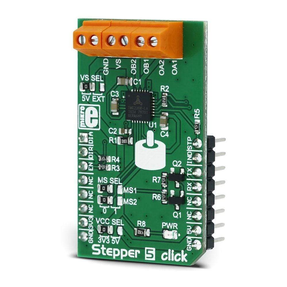
The Stepper 5 Click Board™ is the complete integrated bipolar step motor driver solution, rich with many features that allow silent operation and optimal working conditions for the connected motor.
The specialised TM2208 IC driver from Trinamic company far exceeds the capabilities of similar step motor drivers that are commonly used. In order to achieve such outstanding performances with a wide range of various step motors, this device features several technologies: stealth Chop2 - for silent motor operation; spreadCycle - highly dynamic, motor current control; microPlayer interpolation with 256 micro-steps.
Downloads
Besides these advanced technologies, the TM2208 driver employs a set of other features: full output protection and diagnostics, wide input voltage range and reasonably high currents, internal sensing resistor, highly efficient low RDS ON output MOSFETs, UART communication over a single wire, OTP memory for permanent storing of the working parameters within the specific application, integrated pulse generator for standalone operation, a simple STEP/DIR GPIO interface for driving the motor, and more. All these features allow the developing of highly integrated and reliable step motor driving solution with outstanding performances. It can be used as a direct substitution for simpler step motor drivers in any application that employs one or more step motor drivers.
How Does The Stepper 5 Click Board™ Work?
The Stepper 5 Click Board™ uses the TM2208, a highly integrated bipolar step motor power driver, with the UART interface, from the Trinamic company. As already mentioned, this device features many different features, which allow using the driver almost autonomously. It is equipped with the OTP memory, which can store the working parameters for a specific step motor, avoiding initialization by the MCU, after every Power ON Reset (POR) cycle. Technologies, such as stealthChop2™, spreadCycle™, and microPlayer™, help to achieve high autonomy for the motor driving, using only the STEP and DIR input pins to set the direction and step propagation. Even that can be automated by means of the microPlayer™ technology, reducing the impact on the MCU performance almost completely.

To best describe how to operate this device, it is best to divide its operation into three abstract modes:
A standalone STEP/DIR mode: this mode is also referred to as the legacy mode. The device is operated similar to other pin-driven step motor controllers/drivers – the step propagation is controlled by pulses on the STEP input, and the direction is determined by the DIR pin. MS1 and MS2 pins are used to set the microstep mode from 1:2 step to 1:16 step. VREF pin is used to set the maximum current limit, and on Stepper 5 click, it is set by the R2 resistor, to 1.24A RMS (1.76 peak). The DIAG pin provides diagnostic information, while the INDEX pin provides movement feedback. ENN pin is used to enable or disable the IC. This mode allows the driver to be used as a direct replacement for the simpler driver ICs, thus this mode is called the legacy mode.
A standalone STEP/DIR mode with preprogrammed OTP configuration: the driver IC appears as a standard MCU peripheral device, from the software point of view. A set of configuration and status registers can be used to set the working parameters, which is especially convenient if a specific step motor with known properties is used for the application. The OTP (One Time Programmable) memory is used to store the configuration. It can be stored on the MCU, too. Communication is done via the UART interface, which only requires a single wire for both READ and WRITE operations (a specific message format is utilized to allow this). UART can work on a wide range of baud rates, up to 500K. The UART interface features auto baud rate detection and the CRC generation, allowing for reliable and simple communications to be established with the MCU, even over distances. Once programmed either from the OTP or via the UART, the device can still be driven by the STEP/DIR pins, but the motor performance will be enhanced and fine-tuned to a specific application.
A STEP/DIR mode with the full diagnostics and control : this mode unleashes the full potential of the TM2208. All the parameters can be configured and controlled via the UART, also power and thermal data can be provided back to the MCU for further analysis and optimization. Passive braking and freewheeling modes become available, providing the lowest power consumption for the stop mode (when the step motor is standing still). The control of the microPlayer™ interpolation features become available, allowing more control over micro stepping and yielding even quieter operation. The spreadCycle™ and the stealth Chop2™ technologies offer even more control via the registers. Use of the external pins can be completely bypassed (with the configuration bits), by utilizing the internal programmable step pulse generator. This mode is useful when the absolute top performance is required, with no compromises.
These three modes do not have some special configuration bits that enable them. They are just abstractions of the scenarios in which the Stepper 5 click can be used, therefore they are referred to as the abstract modes. The TM2208 datasheet offers an extensive explanation of all the features of this IC, going into details about how to best use them for a specific application. However, Stepper 5 click comes with the library of functions that simplify its use, along with the example that can be used as a reference for custom projects.
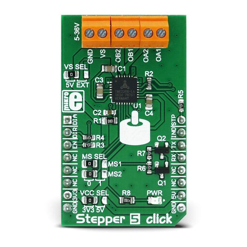
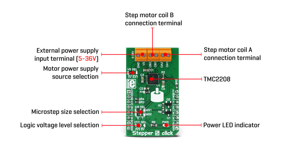
VCC SEL onboard SMD jumper is used to set the logic voltage level for the communication interface. This allows both 3.3V and 5V MCUs to be interfaced with this Click board™. The power supply for the connected bipolar stepper motor can be selected by an onboard SMD jumper labeled as VS SEL, between the 5V rail from the mikroBUS™ and the external power supply. The external power supply can be connected between the VIN and GND inputs of the terminal. The connected voltage should stay within the range between 5V and 36V. The rest of the terminals allow bipolar stepper motor coils to be connected: OA1 and OA2 terminal inputs are used to connect the first coil, while the OB1 and OB2 inputs are used to connect the second motor coil. The microsteps can be configured using the MS SEL jumpers, according to the truth table below the text.
Note that while driving the motor with higher currents, the TM2208 might get warm, affecting its reliability. In that case, proper heat sinks should be used, or the driving current should be reduced.
SPECIFICATIONS
| Type | Stepper |
| Applications | The Stepper 5 Click Board™ is a perfect solution for building various applications that require precise and reliable stepper motor control, such as the movement control of beds, heads, and assemblies of various CNC plotting, milling and 3D printer designs |
| On-board modules | TM2208, a highly integrated bipolar step motor power driver, with the UART interface, from the Trinamic company |
| Key Features | stealth Chop2™, spreadCycle™, and microPlayer™ advanced technologies, full output protection and diagnostics, wide input voltage range and reasonably high currents, highly efficient output MOSFETs, a single wire UART, OTP memory |
| Interface | GPIO,UART |
| Compatibility | mikroBUS |
| Click board size | M (42.9 x 25.4 mm) |
| Input Voltage | 3.3V or 5V |
PINOUT DIAGRAM
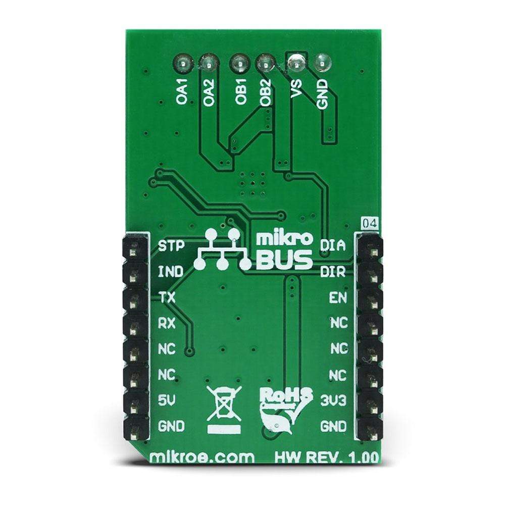
This table shows how the pinout on the Stepper 5 Click Board™ corresponds to the pinout on the mikroBUS™ socket (the latter shown in the two middle columns).
| Notes | Pin |  |
Pin | Notes | |||
|---|---|---|---|---|---|---|---|
| Error Diagnostics OUT | DIA | 1 | AN | PWM | 16 | STP | Step trigger IN |
| Motor Direction IN | DIR | 2 | RST | INT | 15 | IND | Pulse Index OUT |
| Chip Enable IN | EN | 3 | CS | RX | 14 | TX | UART Transmit |
| NC | 4 | SCK | TX | 13 | RX | UART Receive | |
| NC | 5 | MISO | SCL | 12 | NC | ||
| NC | 6 | MOSI | SDA | 11 | NC | ||
| Power supply | +3V | 7 | 3.3V | 5V | 10 | +5V | Power supply |
| Ground | GND | 8 | GND | GND | 9 | GND | Ground |
STEPPER 5 CLICK ELECTRICAL SPECIFICATIONS
| Description | Min | Typ | Max | Unit |
|---|---|---|---|---|
| External power supply voltage | 5 | - | 36 | V |
| Current limit (per channel) | - | - | 1.24 | A |
| Step size (without the interpolation feature) | 1 | - | 1:16 | step |
MICROSTEP RESOLUTION CONFIGURATION
| Step-size | 1:2 | 1:4 | 1:8 | 1:16 |
|---|---|---|---|---|
| MS1 | 1 | 0 | 0 | 1 |
| MS2 | 0 | 1 | 0 | 1 |
ONBOARD SETTINGS AND INDICATORS
| Label | Name | Default | Description |
|---|---|---|---|
| PWR | PWR | - | Power LED indicator |
| MS1 - MS2 | MS SEL | Left | Step size selection: left position LOW (0), right position HIGH (1) |
| PWR IN | GND, VS | - | The external power supply connector |
| OA | OA1, OA2 | - | Stepper motor coil A connector |
| OB | OB1, OB2 | - | Stepper motor coil B connector |
| VCC SEL | VCC SEL | Left | Logic voltage level selection: left position - 3.3V; right position - 5V |
| VS SEL | VS SEL | Left | External power supply source selection: left position - 5V from the mikroBUS™; right position - external power supply |
| General Information | |
|---|---|
Part Number (SKU) |
MIKROE-2624
|
Manufacturer |
|
| Physical and Mechanical | |
Weight |
0.021 kg
|
| Other | |
Country of Origin |
|
HS Code Customs Tariff code
|
|
EAN |
8606018713325
|
Warranty |
|
Frequently Asked Questions
Have a Question?
Be the first to ask a question about this.


