Key Features
Overview
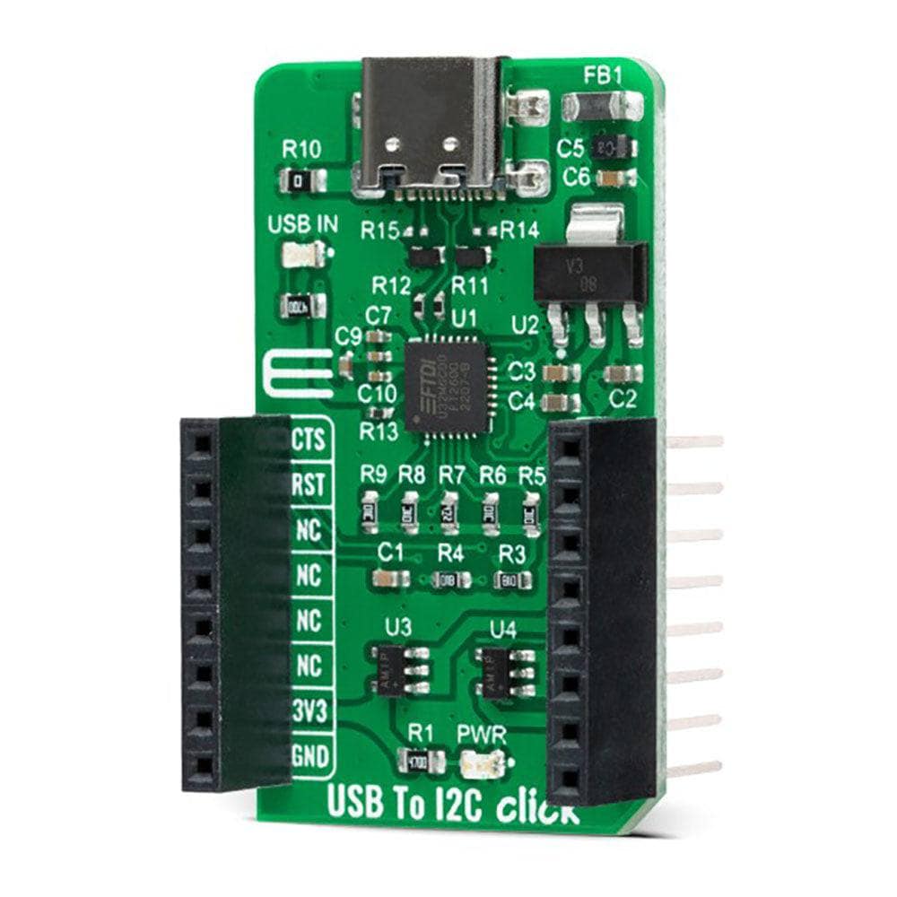
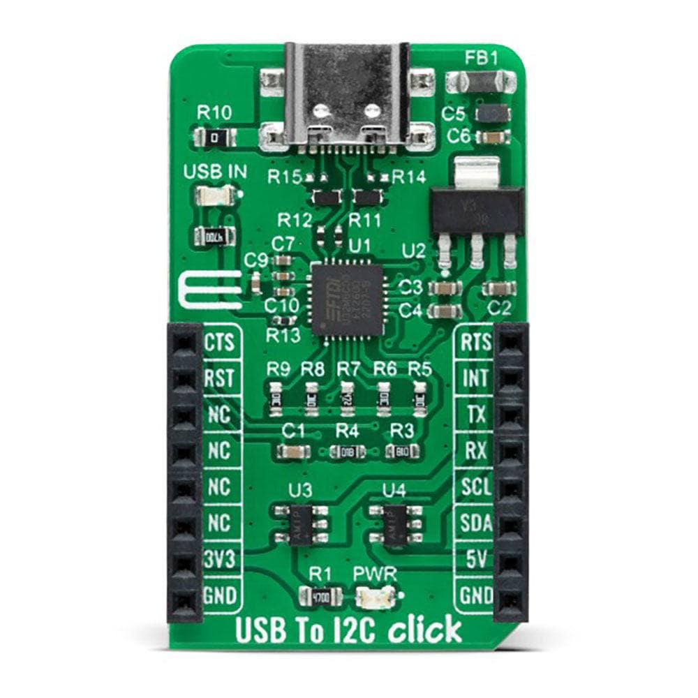
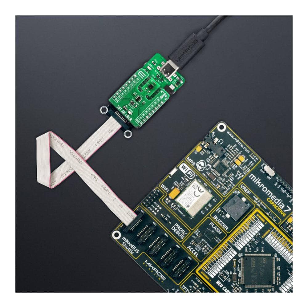
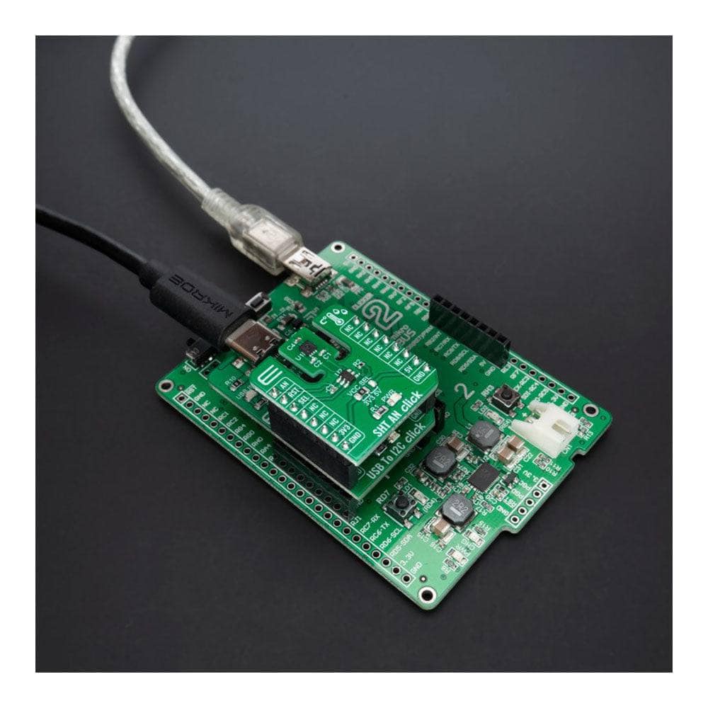
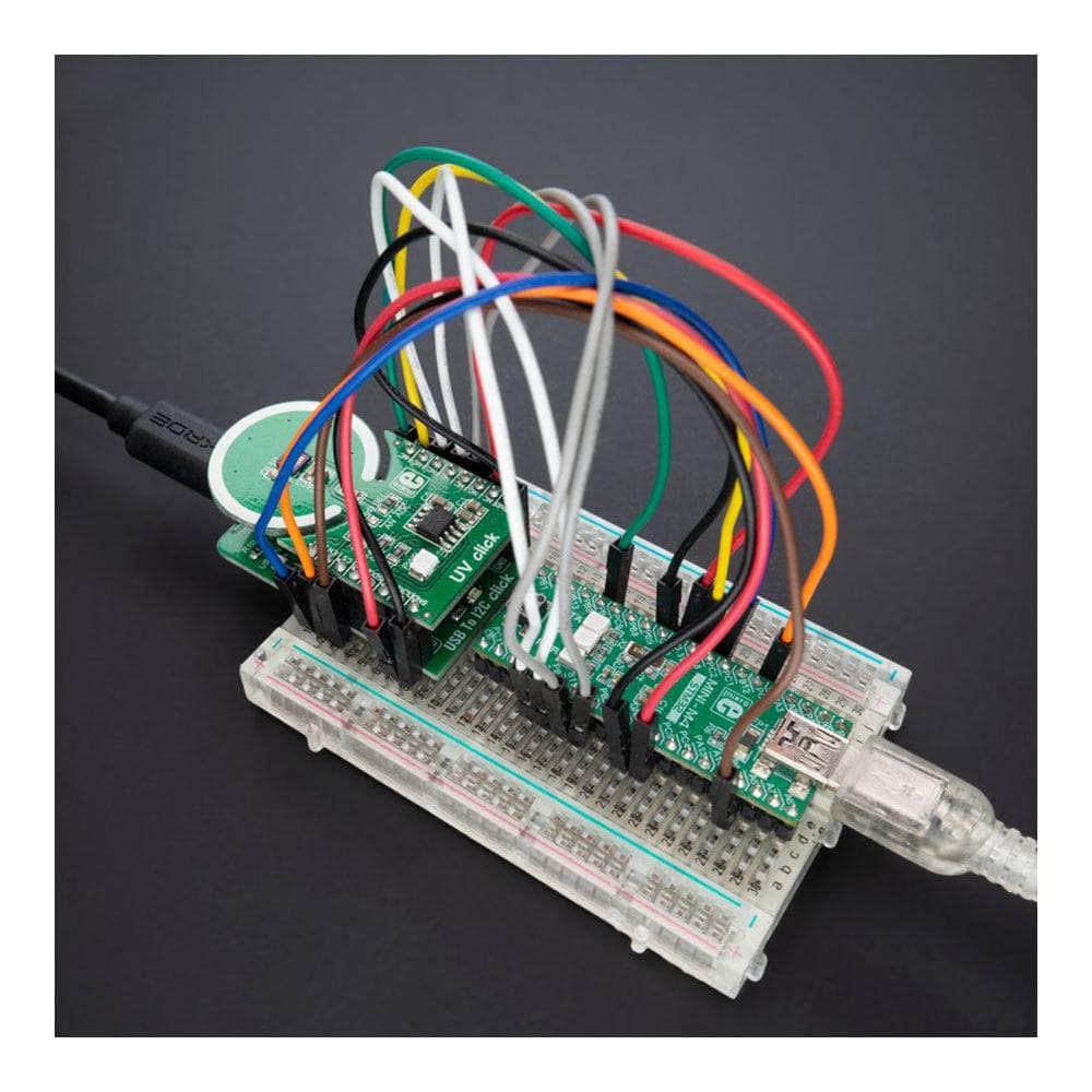
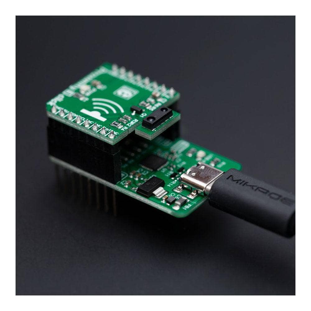
The USB to I2C Click Board™ is a compact add-on board with a general-purpose USB to I2C serial interface. This board features the FT260, an interface device controller that provides a bridge between standard USB Human Interface Device (HID) class drivers and an I2C or UART slave device from FTDI. The FT260 is highly-integrated with a USB 2.0-compliant full-speed (12Mbps) transceiver, oscillator, LDO regulator, and on-chip eFUSE. It is supported by most operating systems where a custom driver is not required. With the possibility of use as a standalone device, this Click board™ provides an ideal, fast-to-implement bridge between USB and either UART or I2C peripherals.
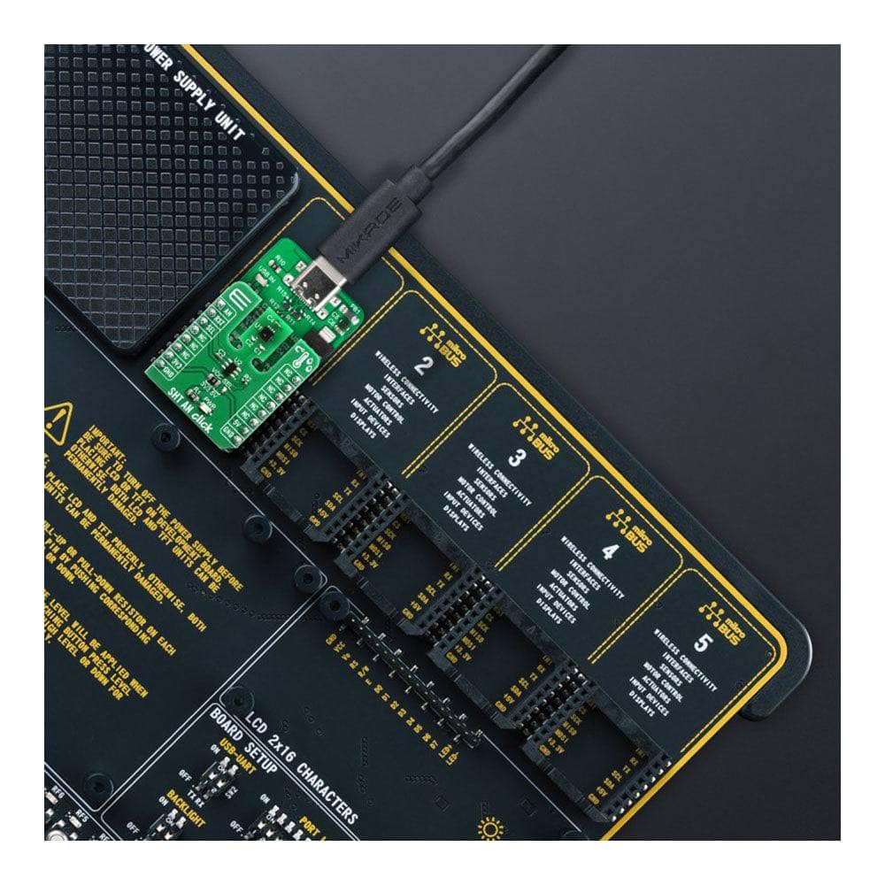
The USB to I2C Click Board™ is supported by a mikroSDK compliant library, which includes functions that simplify software development. This Click board™ comes as a fully tested product, ready to be used on a system equipped with the mikroBUS™ socket.
Downloads
How Does The USB to I2C Click Board™ Work?
The USB to I2C Click Board™ as its foundation uses the FT260, a USB device that supports I2C and UART communication through standard USB HID class interfaces from FTDI. It provides the bridge function between a standard USB HID class driver and an I2C or UART slave device. This highly integrated IC comes with a USB2.0 compliant full-speed transceiver, oscillator as the source of the operating clock, LDO regulator for the entire chip operating power source, eFUSE for basic customization, and automatic scanning mechanism of EEPROM for advanced customization. The USB HID class is natively supported by most operating systems with no requirements for custom drivers.
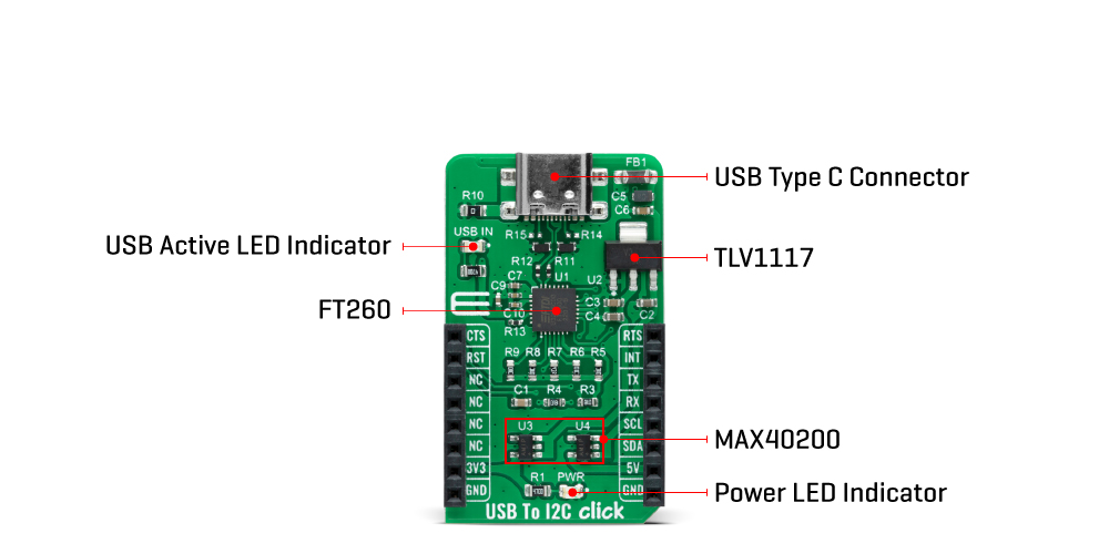
The USB to I2C Click Board™ can communicate with MCU via UART or I2C interface. The FT260 uses the UART interface with commonly used UART RX and TX pins and hardware flow control pins UART CTS and RTS (Clear to Send and Ready to Send) to transmit and exchange data with the host MCU or using the I2C interface, which can also act as a Master with a maximum I2C bus speed of up to 3.4Mbit/s. These two interfaces exist concurrently and can be selected independently according to the application.
In addition, the USB to I2C Click Board™ also has an active-low reset signal routed on the RST pin of the mikroBUS™ socket that activates a hardware reset of the chip and a possibility of a remote wake-up function. If the operating system supports remote wake-up and allows external hardware to wake it, the FT260 can be resumed by the INT pin, defaulted as wake-up, triggering a resume signal on the USB bus to wake up the USB host. If this function is not used, this pin behaves like a standard interrupt pin.
The USB to I2C Click Board™ can operate with both 3.3V and 5V logic voltage levels. Considering that the board can be powered via USB and used as a standalone device (USB active voltage level is visually indicated with a blue LED marked USB IN), using an additional LDO, the TLV1117, in this way, the existence of the voltage of both mikroBUS™ power lines is ensured. An LDO and both mikroBUS™ power rails also have protection in the form of MAX40200 diodes to prevent any unwanted back voltage.
The USB to I2C Click Board™ must complete the proper logic voltage level conversion before use with MCUs with different logic levels. However, the Click board™ comes equipped with a library containing functions and an example code that can be used, as a reference, for further development.
SPECIFICATIONS
| Type | USB |
| Applications | Can be used as a bridge between USB and either UART or I2C peripherals |
| On-board modules | FT260 - USB device that supports I2C and UART communication through standard USB HID class interfaces from FTDI |
| Key Features | Full speed HID class USB device, USB2.0 compliant with entire USB protocol handled on the chip, supported by most operation systems, custom driver is not required, I2C Master interface, standalone operation, and more |
| Interface | I2C,UART,USB |
| Compatibility | mikroBUS |
| Click board size | M (42.9 x 25.4 mm) |
| Input Voltage | 3.3V or 5V |
PINOUT DIAGRAM
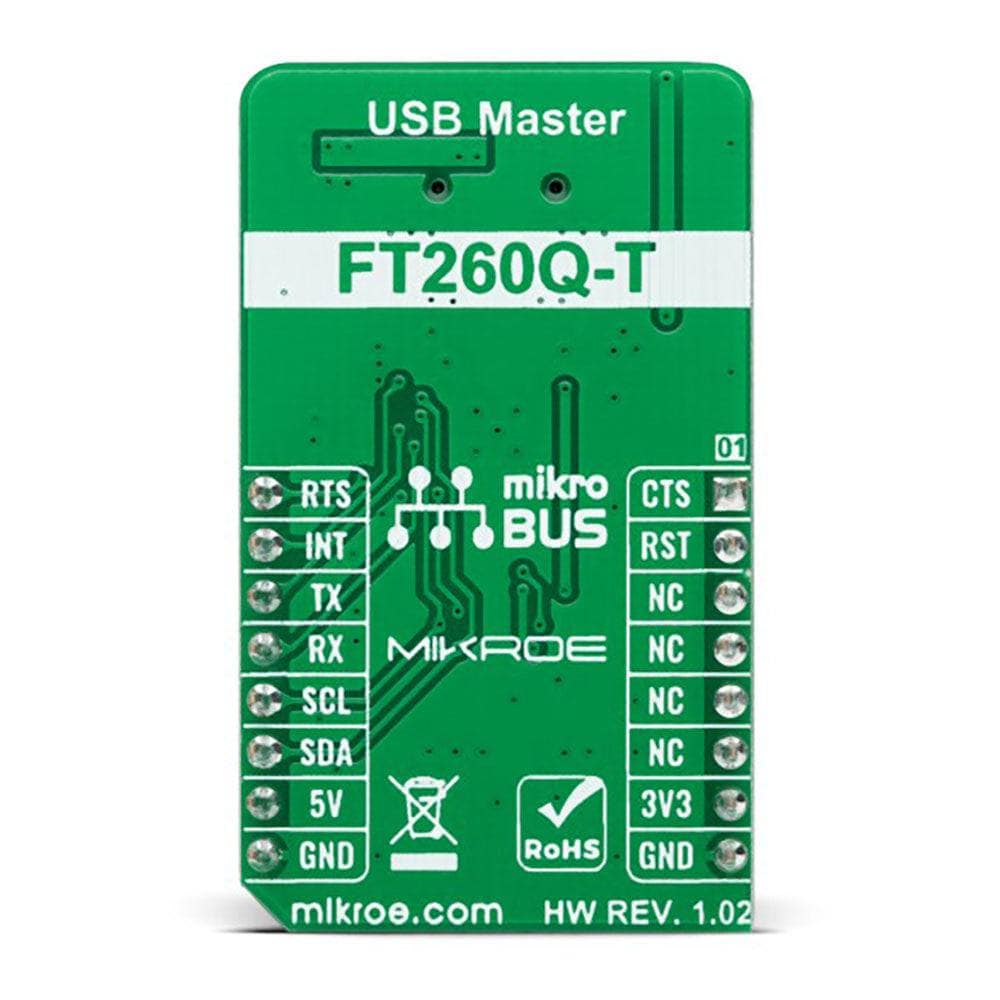
This table shows how the pinout of the USB to I2C Click Board™ corresponds to the pinout on the mikroBUS™ socket (the latter shown in the two middle columns).
| Notes | Pin |  |
Pin | Notes | |||
|---|---|---|---|---|---|---|---|
| UART CTS | CTS | 1 | AN | PWM | 16 | RTS | UART RTS |
| RESET | RST | 2 | RST | INT | 15 | INT | Wake-up / Interrupt |
| NC | 3 | CS | RX | 14 | TX | UART TX | |
| NC | 4 | SCK | TX | 13 | RX | UART RX | |
| NC | 5 | MISO | SCL | 12 | SCL | I2C Clock | |
| NC | 6 | MOSI | SDA | 11 | SDA | I2C Data | |
| Power Supply | 3.3V | 7 | 3.3V | 5V | 10 | 5V | Power Supply |
| Ground | GND | 8 | GND | GND | 9 | GND | Ground |
ONBOARD SETTINGS AND INDICATORS
| Label | Name | Default | Description |
|---|---|---|---|
| LD1 | PWR | - | Power LED Indicator |
| LD2 | USB IN | - | USB Active LED Indicator |
USB TO I2C CLICK ELECTRICAL SPECIFICATIONS
| Description | Min | Typ | Max | Unit |
|---|---|---|---|---|
| Supply Voltage | 3.3 | - | 5 | V |
| Data Rate | - | - | 12 | Mbps |
| Operating Temperature Range | -40 | +25 | +85 | °C |
| General Information | |
|---|---|
Part Number (SKU) |
MIKROE-5312
|
Manufacturer |
|
| Physical and Mechanical | |
Weight |
0.02 kg
|
| Other | |
Country of Origin |
|
HS Code Customs Tariff code
|
|
EAN |
8606027387760
|
Warranty |
|
Frequently Asked Questions
Have a Question?
Be the first to ask a question about this.


