


Mikroelektronika d.o.o.
I2C MUX 7 Click Board™
I2C MUX 7 Click Board™
SKU: MIKROE-5069
Couldn't load pickup availability


Overview
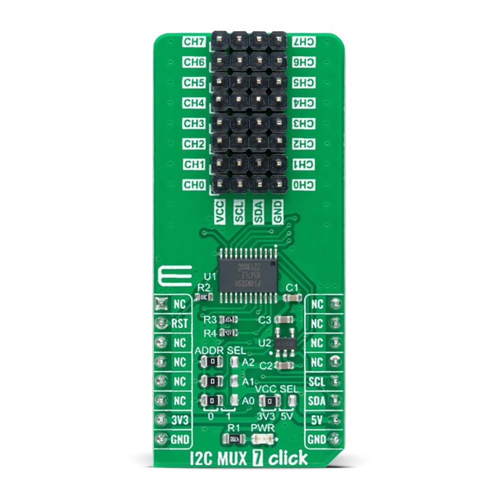
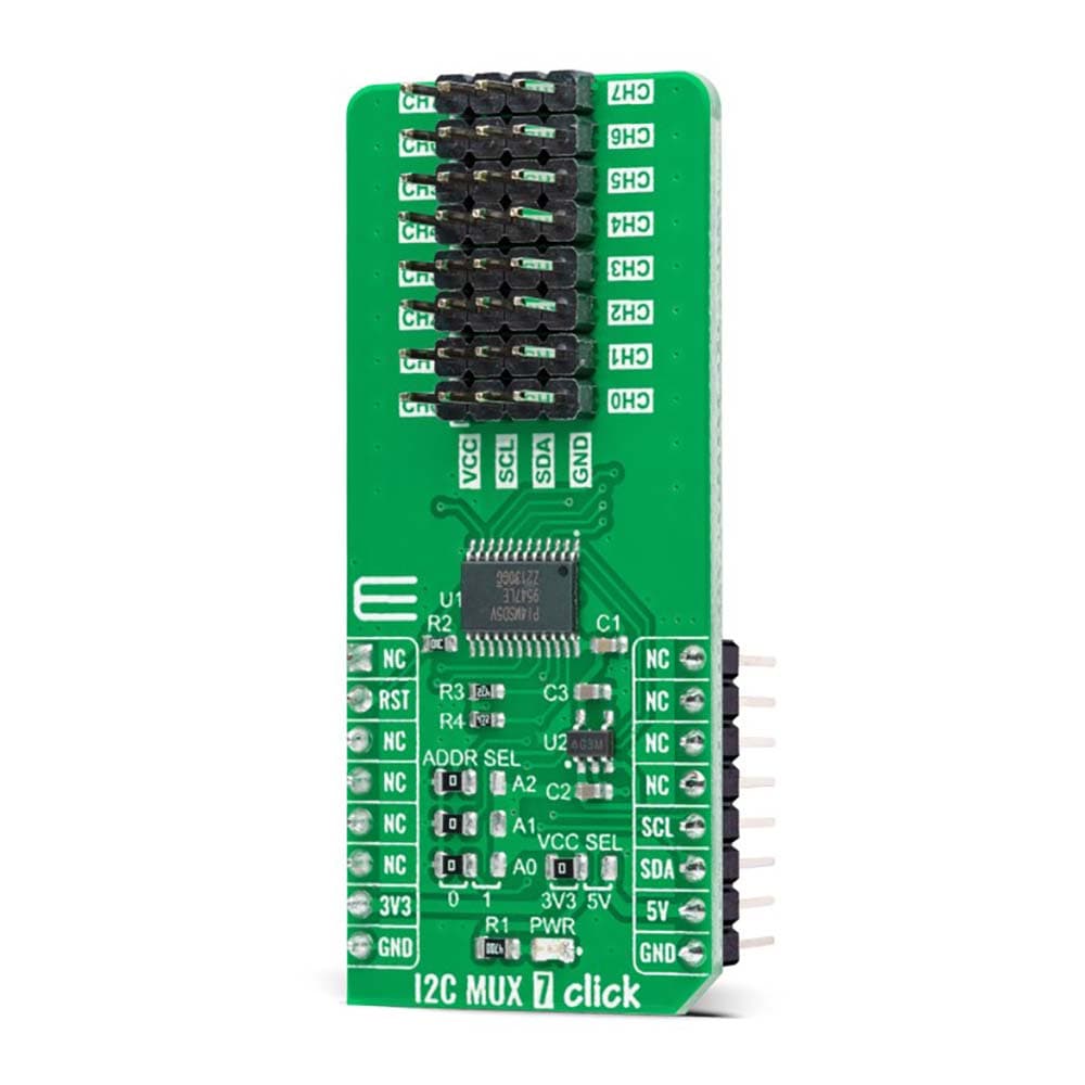
The I2C MUX 7 Click Board™ is a compact add-on board representing a bidirectional selector dedicated to applications with I2C slave address conflicts. This board features the PI4MSD5V9547, an octal bidirectional translating multiplexer controlled by the I2C-bus from Texas Instruments. Only one SCL/SDA channel can be selected at a time, determined by the contents of the programmable control register. The board powers up with Channel 0 connected, allowing immediate communication between the Master and downstream devices on that channel. The PI4MSD5V9547 also supports hot insertion, has a low Stand-by current, and has no glitch during the Power-Up sequence. This Click board™ is suitable for a wide range of applications from industrial to medical, communications, and automotive systems.
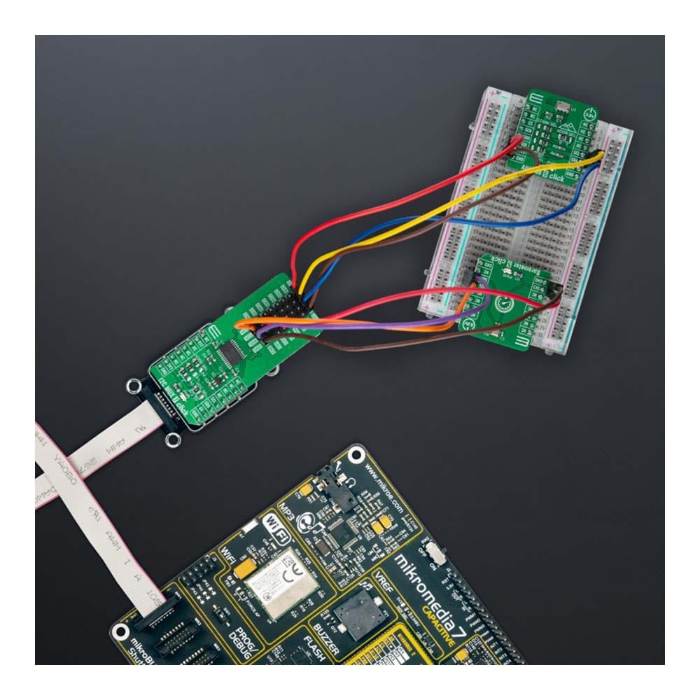
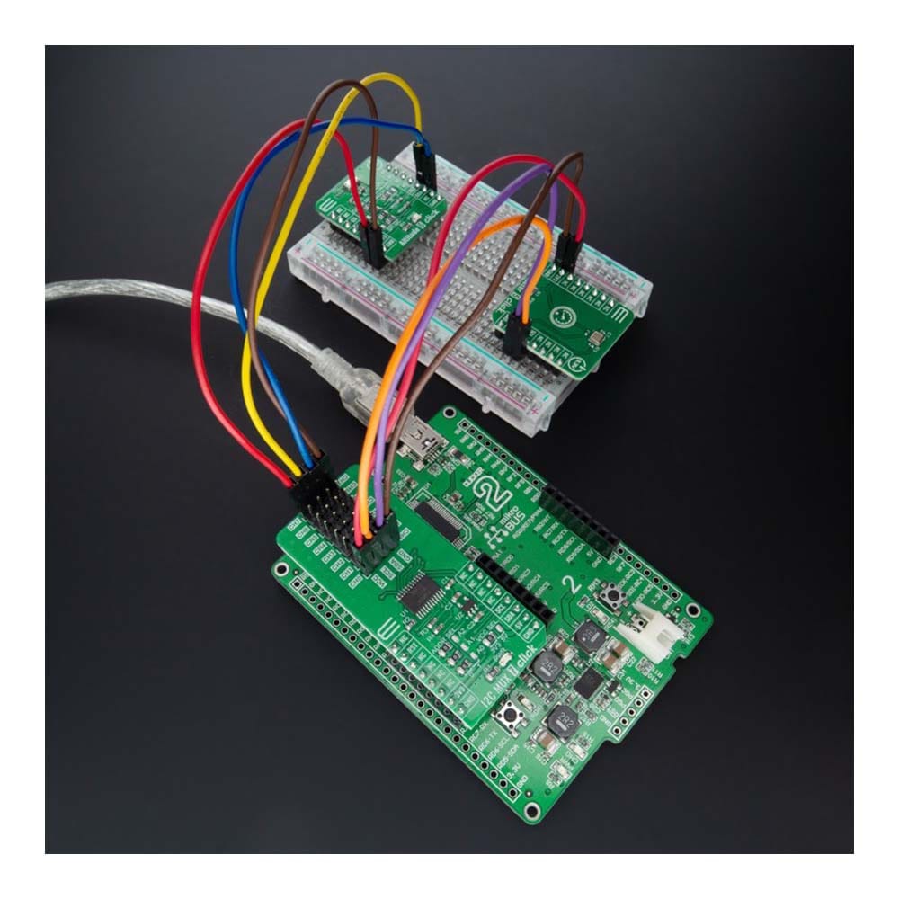
The I2C MUX 7 Click Board™ is supported by a mikroSDK compliant library, which includes functions that simplify software development. This Click board™ comes as a fully tested product, ready to be used on a system equipped with the mikroBUS™ socket.
Downloads
How Does The I2C MUX 7 Click Board™ Work?
The I2C MUX 7 Click Board™ as its foundation uses the PI4MSD5V9547, a low voltage octal bidirectional translating multiplexer with an active-low reset input controlled through the I2C serial interface from Texas Instruments. The master SCL/SDA signal pair is directed to eight channels CH0-CH7, where only one SCL/SDA channel can be selected at a time, determined by the contents of the programmable control register. The board powers up with Channel 0 connected, allowing immediate communication between the Master and downstream devices on that channel.
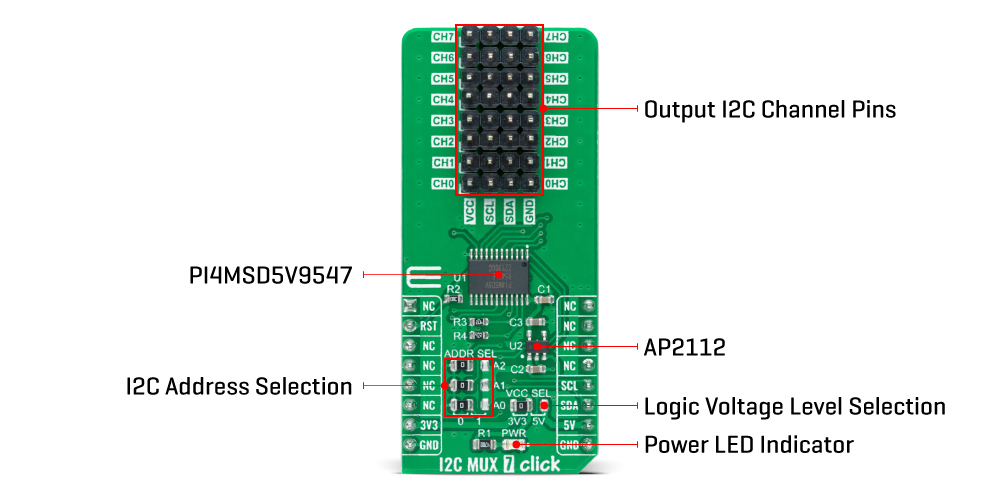
The I2C MUX 7 Click Board™ includes a low dropout linear regulator AP2112 from Diodes Incorporated to provide the 1.8V supply voltage for the PI4MSD5V9547. When power is applied to IC, an internal Power-On Reset (POR) holds the PI4MSD5V9547 in a reset condition until the power supply reaches the POR voltage level. At this point, the reset condition is released, and the PI4MSD5V9547 registers and I2C-bus state machine are initialized to their default states (all zeroes), causing deselection of all channels.
The I2C MUX 7 Click Board™ communicates with MCU using the standard I2C 2-Wire interface that supports Standard-Mode (100 kHz) and Fast-Mode (400 kHz) operation. The PI4MSD5V9547 has a 7-bit slave address with the first five MSBs fixed to 1110. The address pins A0, A1, and A2, are programmed by the user and determine the value of the last three LSBs of the slave address, which can be selected by onboard SMD jumpers labelled as ADDR SEL, allowing selection of the slave address LSBs. Alongside the internal Power-On Reset (POR) function, this board also has an active-low reset signal routed on the RST pin of the mikroBUS™ socket used to recover from a bus-fault condition. When this signal is asserted low, the PI4MSD5V9547 resets its registers alongside with I2C state machine and deselects all channels.
The I2C MUX 7 Click Board™ can operate with both 3.3V and 5V logic voltage levels selected via the VCC SEL jumper. This way, it is allowed for both 3.3V and 5V capable MCUs to use the communication lines properly. However, the Click board™ comes equipped with a library containing easy-to-use functions and an example code that can be used, as a reference, for further development.
SPECIFICATIONS
| Type | I2C |
| Applications | The I2C MUX 7 Click Board™ can be used for a wide range of applications from industrial to medical, communications, and automotive systems |
| On-board modules | PI4MSD5V9547 - octal bidirectional translating multiplexer controlled by the I2C-bus from Texas Instruments |
| Key Features | Low power consumption, reset feature, channel selection via I2C bus, Power-Up with one channel ON, no glich on Power-On, support hot insertion, and more |
| Interface | I2C |
| Compatibility | mikroBUS |
| Click board size | L (57.15 x 25.4 mm) |
| Input Voltage | 3.3V or 5V |
PINOUT DIAGRAM
This table shows how the pinout of the I2C MUX 7 Click Board™ corresponds to the pinout on the mikroBUS™ socket (the latter shown in the two middle columns).
| Notes | Pin | Pin | Notes | ||||
|---|---|---|---|---|---|---|---|
| NC | 1 | AN | PWM | 16 | NC | ||
| Reset | RST | 2 | RST | INT | 15 | NC | |
| NC | 3 | CS | RX | 14 | NC | ||
| NC | 4 | SCK | TX | 13 | NC | ||
| NC | 5 | MISO | SCL | 12 | SCL | I2C Clock | |
| NC | 6 | MOSI | SDA | 11 | SDA | I2C Data | |
| Power Supply | 3.3V | 7 | 3.3V | 5V | 10 | 5V | Power Supply |
| Ground | GND | 8 | GND | GND | 9 | GND | Ground |
ONBOARD SETTINGS AND INDICATORS
| Label | Name | Default | Description |
|---|---|---|---|
| LD1 | PWR | - | Power LED Indicator |
| JP1 | VCC SEL | Left | Logic Level Voltage Selection 3V3/5V: Left position 3V3, Right position 5V |
| JP2-JP4 | ADDR SEL | Left | I2C Address Selection 0/1: Left position 0, Right position 1 |
| J1-J8 | CH0-CH7 | Populated | Output I2C Channel Pins |
I2C MUX 7 CLICK ELECTRICAL SPECIFICATIONS
| Description | Min | Typ | Max | Unit |
|---|---|---|---|---|
| Supply Voltage | 3.3 | - | 5 | V |
| ON Resistance | - | - | 70 | Ω |
| Operating Temperature Range | -40 | +25 | +85 | °C |
| General Information | |
|---|---|
Part Number (SKU) |
MIKROE-5069
|
Manufacturer |
|
| Physical and Mechanical | |
Weight |
0.02 kg
|
| Other | |
EAN |
8606027389429
|
Frequently Asked Questions
Have a Question?
Be the first to ask a question about this.