Overview
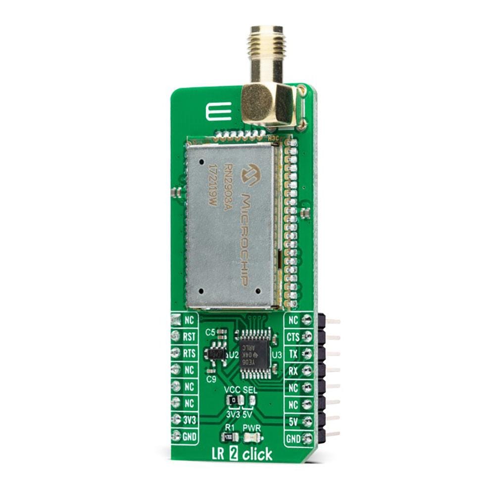
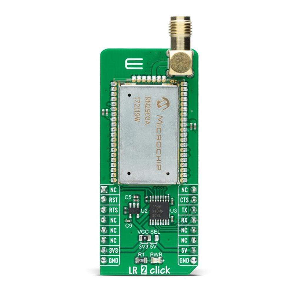
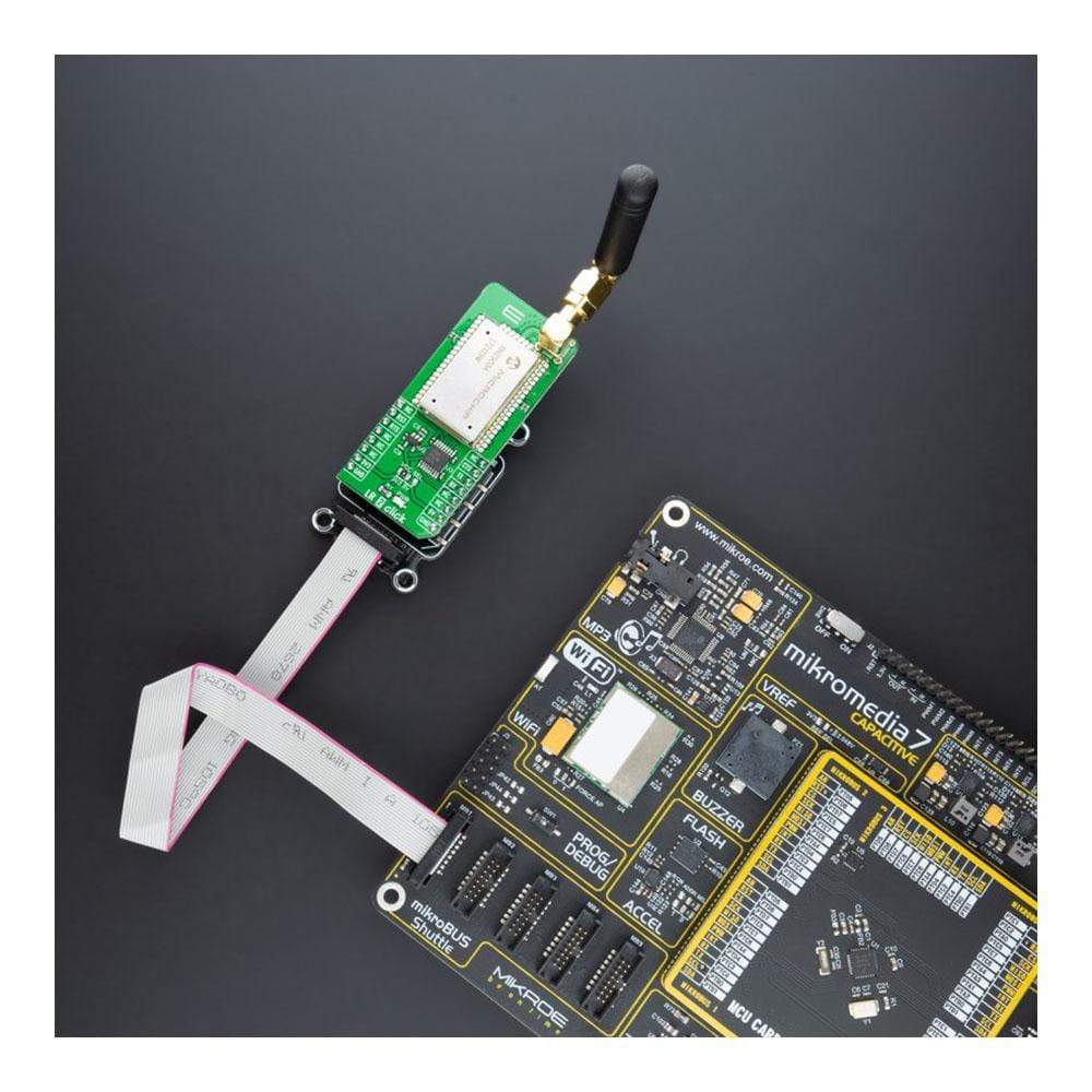
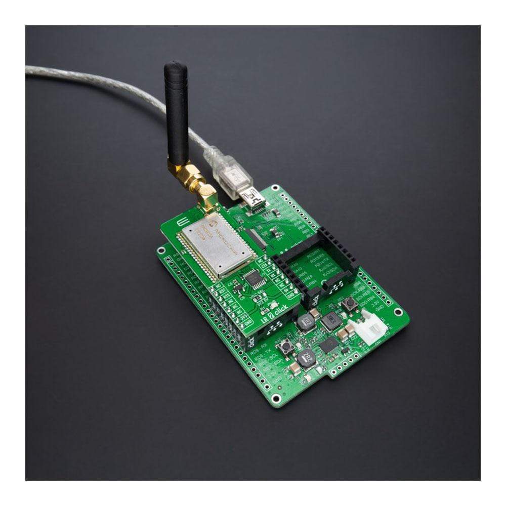
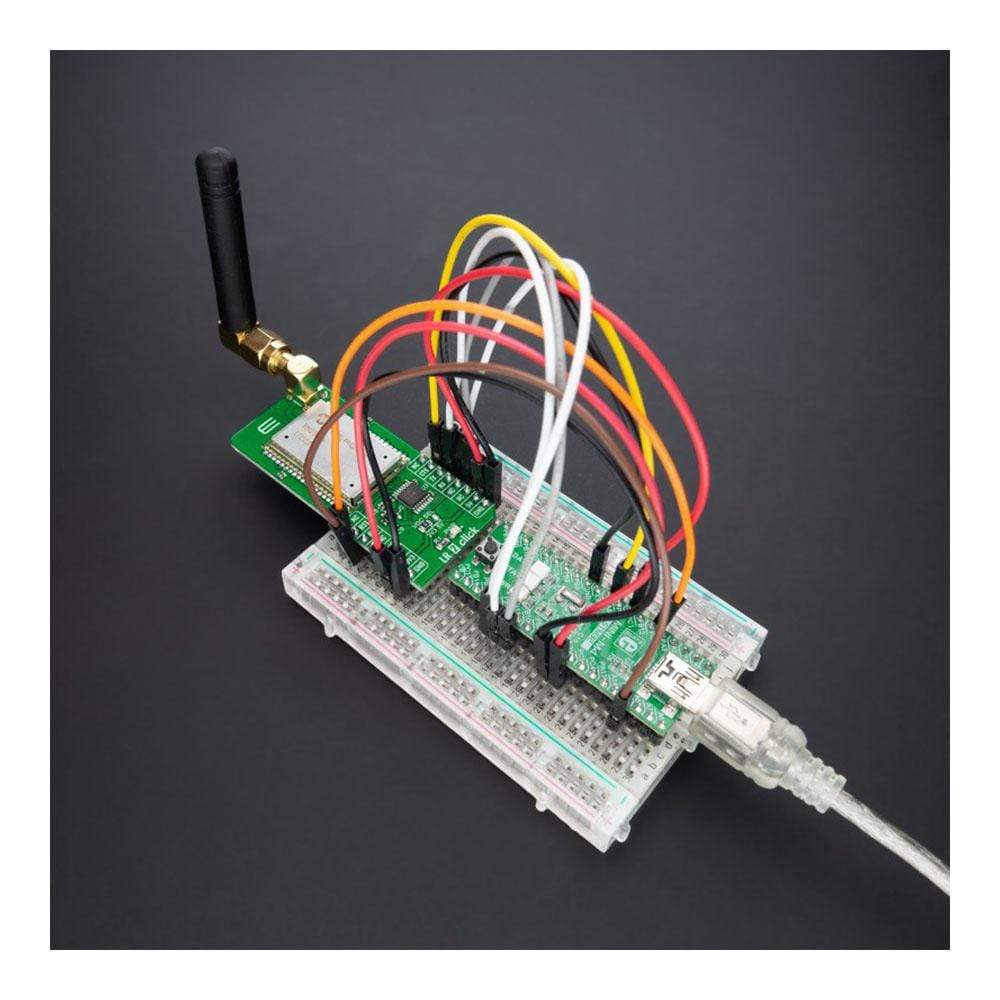
The LR 2 Click Board™ is a compact add-on board that contains a low-power, long-range transceiver. This board features the RN2903, RF technology-based SRD transceiver, which operates at a frequency of 915MHz from Microchip Technology. This Click Board™ features an embedded LoRaWAN Class A compliant stack, providing a long-range spread spectrum communication with high interference immunity. The RN2903 module is fully compliant with the United States (FCC) and Canada (IC) regulations combined with the advanced and straightforward command interface allowing easy integration into the final application. This Click Board™ offers an easy and reliable solution for developing highly integrated long-range IoT networks, security systems, alarm networks, building control, M2M interfaces, and similar applications that require simple and reliable networking solutions.
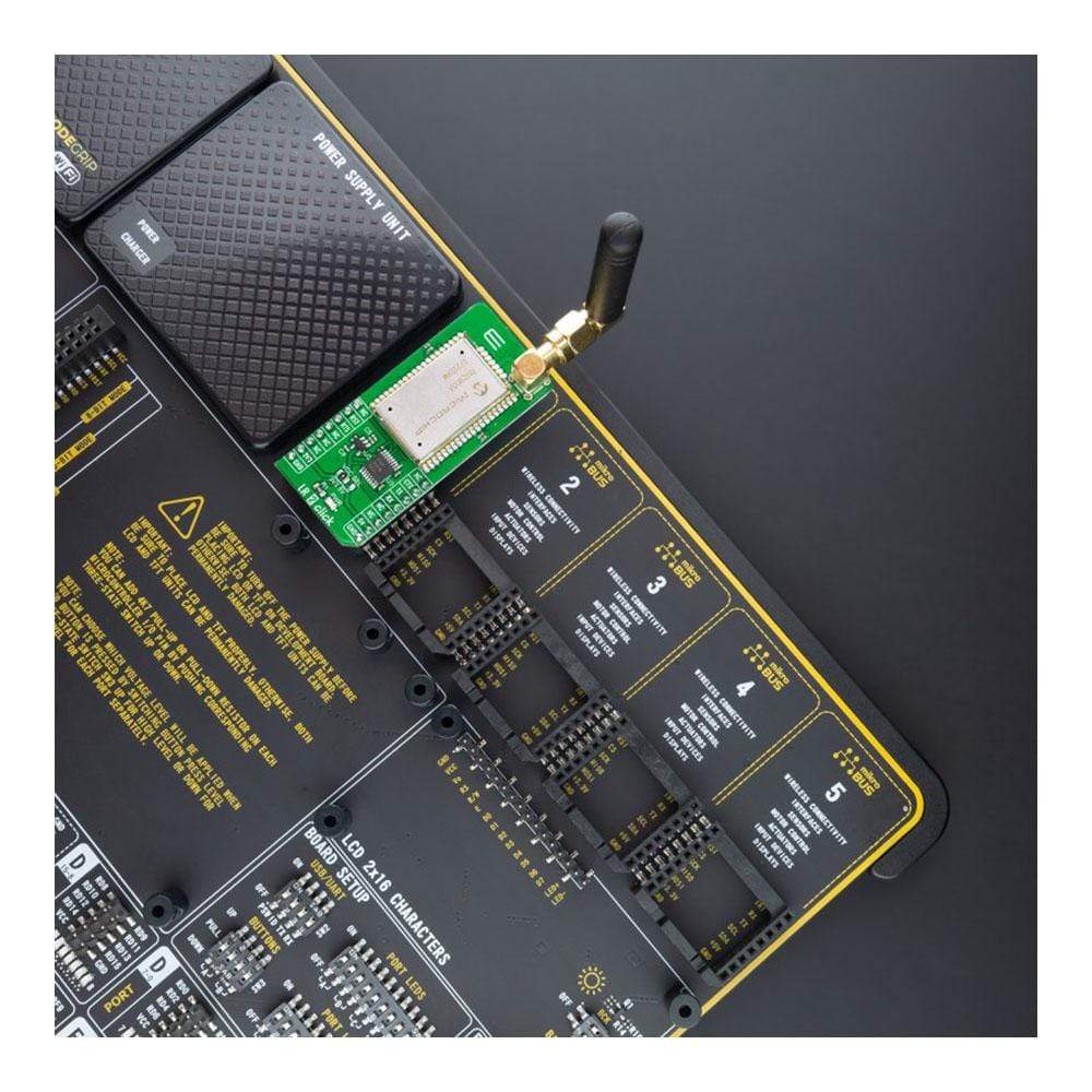
The LR 2 Click Board™ is supported by a mikroSDK compliant library, which includes functions that simplify software development. This Click Board™ comes as a fully tested product, ready to be used on a system equipped with the mikroBUS™ socket.
Downloads
How Does The LR 2 Click Board™ Work?
The LR 2 Click Board™ as its foundation uses the RN2903, a low-power long-range RF technology-based transceiver module from Microchip Technology. It features the Class A LoRaWAN compliant stack, optimized for robust LoRaWAN networking, immune to interferences, and suitable for long-range wireless operation. It offers a long-range spread spectrum communication with high interference immunity. A receiver with a sensitivity of -148dBm combined with the 18.5dBm integrated amplifier allows for extended range links that can achieve up to 15km in an open area (by the module manufacturer specification). The LR 2 Click Board™ offers data rates of 300kbps with FSK modulation and 12500bps with LoRa Technology modulation and is associated with the 915MHz ISM band suitable for applications in the United States, Canada, Australia, and New Zealand.
To join a LoRaWAN network, the RN2903 requires a LoRaWAN concentrator/gateway. The endpoint device has to use a unique endpoint address, an application session key, and a network session key. The first method is called over-the-air activation (OTAA), where these keys are issued after a specific join procedure. The second method is to assign these keys manually, using UART commands. This method is called activation by personalization (ABP) and can be prone to some security issues. In any case, before an end-device can communicate on the LoRaWAN network, it must be activated.
The LR 2 Click Board™ communicates with MCU using the UART interface with commonly used UART RX and TX pins, including the hardware flow control pins CTS and RTS (Clear to Send, Ready to Send) at data rates up to 57600bps for the data transfer. There are three groups of commands used to configure and operate the separate layers of the RN2903 (SYSTEM, MAC, and RADIO). Each of these layers is controlling a specific area of the module, and every UART command starts with one of the three keywords, which represent an abbreviation of the layer name they are controlling. The module is also equipped with a non-volatile memory (EEPROM) for storing the configuration settings and some additional data.
Explanation of all the configuration parameters, as well as the in-depth explanation of each feature of the RN2903 module, can be found in the Command Reference User's Guide. Please note that improper settings of some parameters might render the device unresponsive. Also, this Click board™ can be reset through the Hardware Reset pin, labelled as RST on the mikroBUS™ socket, by setting this pin to a low logic state.
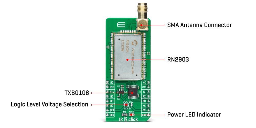
The LR 2 Click Board™ features the SMA antenna connector with an impedance of 50Ω, so it can be equipped with the appropriate 915MHz compliant antenna that MikroE has in its offer.
The LR 2 Click Board™ can operate with both 3.3V and 5V logic voltage levels selected via the VCC SEL jumper. A proper logic voltage level conversion is performed by the TXB0106 voltage level shifter, while the LDO ensures that recommended values power the module. This allows for both 3.3V and 5V capable MCUs to use the UART communication lines properly. However, the Click board™ comes equipped with a library containing easy-to-use functions and an example code that can be used, as a reference, for further development.
SPECIFICATIONS
| Type | LoRa |
| Applications | The LR 2 Click Board™ can be used for developing highly integrated long-range IoT networks, security systems, alarm networks, building control, M2M interfaces, and similar applications that require simple and reliable networking solutions. |
| On-board modules | RN2903 - low-power long-range RF technology-based transceiver module from Microchip Technology |
| Radio Region | North America |
| Key Features | Modem is compliant for use in USA (FCC), Canada (IC), Australia and New Zealand. Sensitivity: -146 dBm. Embeds LoRaWAN® Class A protocol stack |
| Interface | UART |
| Compatibility | mikroBUS |
| Click board size | L (57.15 x 25.4 mm) |
| Input Voltage | 3.3V or 5V |
PINOUT DIAGRAM
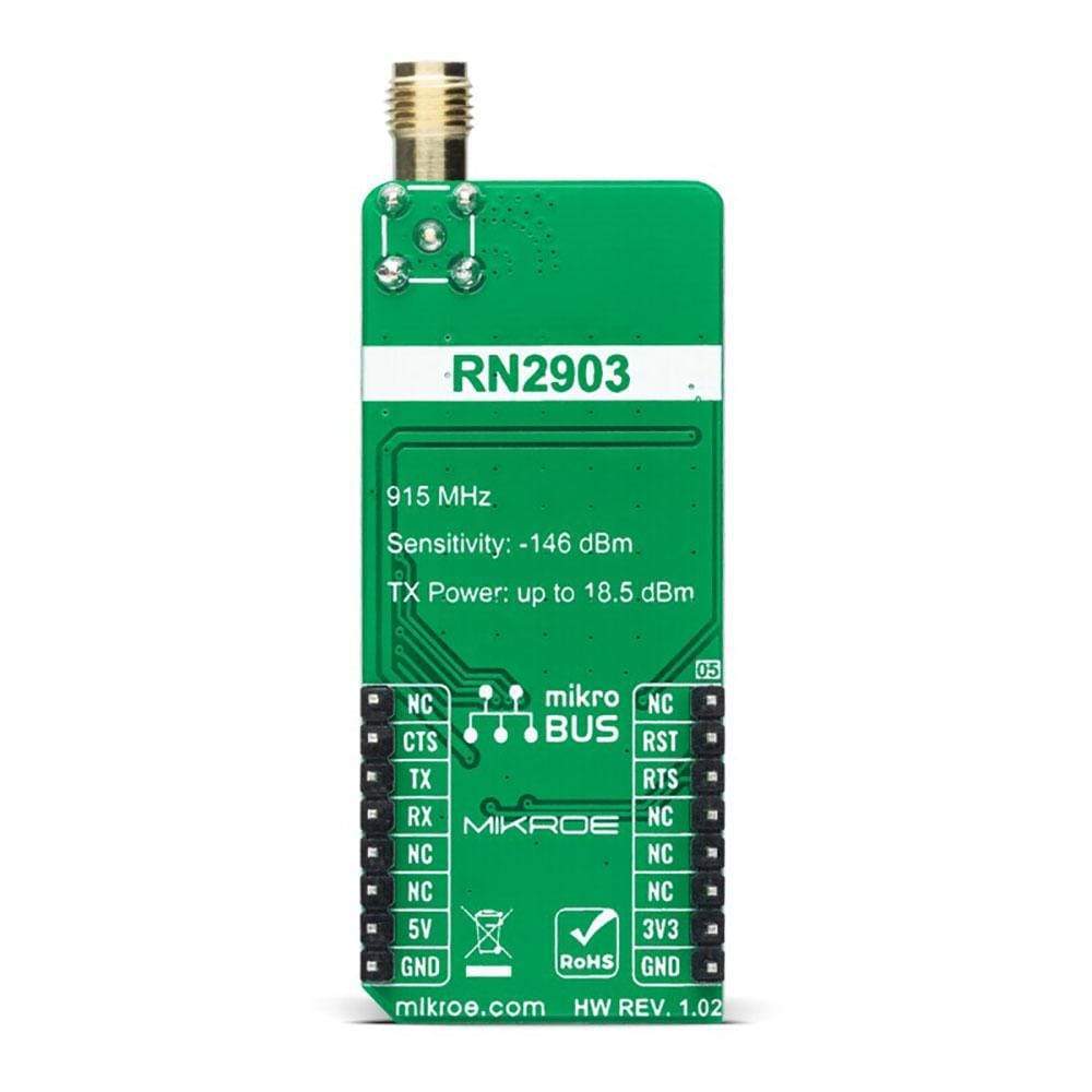
This table shows how the pinout of LR 2 Click Board™ corresponds to the pinout on the mikroBUS™ socket (the latter shown in the two middle columns).
| Notes | Pin |  |
Pin | Notes | |||
|---|---|---|---|---|---|---|---|
| NC | 1 | AN | PWM | 16 | NC | ||
| Reset | RST | 2 | RST | INT | 15 | CTS | UART Clear-To-Send |
| UART Ready-To-Send | RTS | 3 | CS | RX | 14 | TX | UART TX |
| NC | 4 | SCK | TX | 13 | RX | UART RX | |
| NC | 5 | MISO | SCL | 12 | NC | ||
| NC | 6 | MOSI | SDA | 11 | NC | ||
| Power supply | +3.3V | 7 | 3.3V | 5V | 10 | +5V | Power supply |
| Ground | GND | 8 | GND | GND | 9 | GND | Ground |
ONBOARD SETTINGS AND INDICATORS
| Label | Name | Default | Description |
|---|---|---|---|
| LD1 | PWR | - | Power LED indicator |
| JP1 | VCC SEL | Left | Logic Level Voltage Selection 3V3/5V: Left position 3V3, Right position 5V |
LR 2 CLICK ELECTRICAL SPECIFICATIONS
| Description | Min | Typ | Max | Unit |
|---|---|---|---|---|
| Supply Voltage | 3.3 | - | 5 | V |
| Operating Frequency Range | 902 | 915 | 928 | MHz |
| UART interface baud rate | - | 57600 | - | bps |
| Operating Temperature Range | -40 | +25 | +85 | °C |
| General Information | |
|---|---|
Part Number (SKU) |
MIKROE-4615
|
Manufacturer |
|
| Physical and Mechanical | |
Weight |
0.02 kg
|
| Other | |
Country of Origin |
|
HS Code Customs Tariff code
|
|
EAN |
8606027382420
|
Warranty |
|
Frequently Asked Questions
Have a Question?
Be the first to ask a question about this.

