Overview
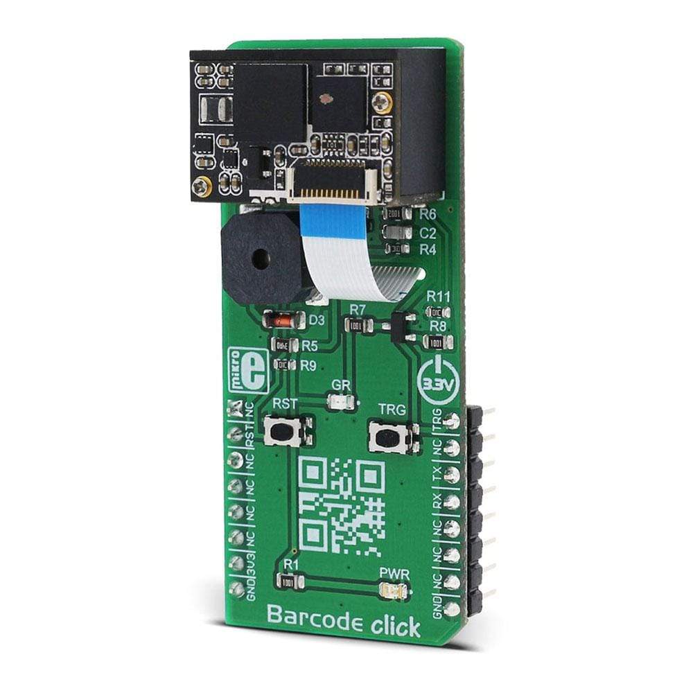
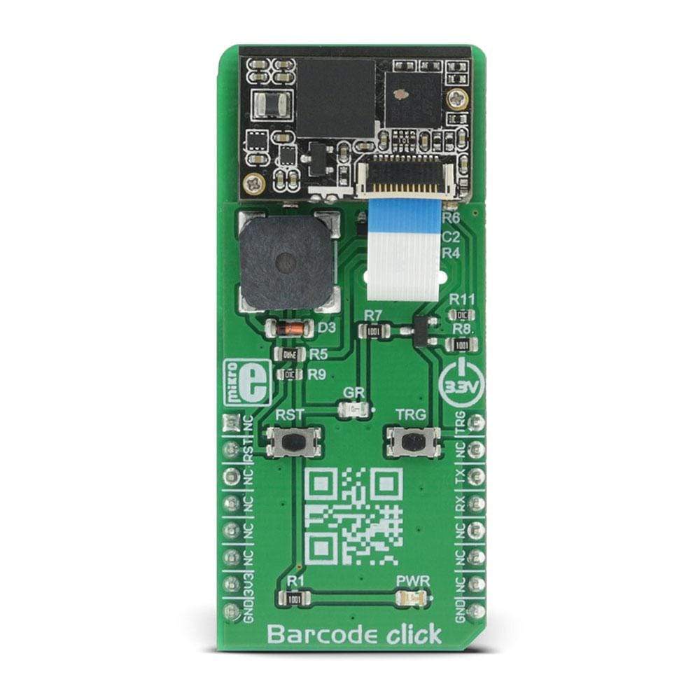
The Barcode Click Board™ is a very fast and agile barcode scanner on a Click Board™, which is compliant with a wide range of different 1D and 2D barcode protocols. The barcode scanner module is equipped with the micro USB port; thus, it can work both as a standalone device and a standard Click Board™, which communicates with the MCU via the RX, TX, RST and PWM pin of the mikroBUS. The barcode module has two red LEDs, used to illuminate the area in low light conditions.
Also, the Barcode Click Board™ features two pushbuttons, used to control the device when working as a standalone device.
Downloads
The Barcode Click Board™ is a very fast and agile barcode scanner on a Click Board™, which is compliant with a wide range of different 1D and 2D barcode protocols. The barcode scanner module is equipped with the micro USB port; thus, it can work both as a standalone device and a standard Click Board™, which communicates with the MCU via the RX, TX, RST and PWM pin of the mikroBUS. The barcode module has two red LEDs, used to illuminate the area in low light conditions. Also, Barcode Click Board™ features two push buttons, used to control the device when working as a standalone device.
The barcode scanner module used for the Barcode Click Board™, is the LV3296 made by Rakinda company, a compact barcode scanner module armed with the Rakinda patented UIMG® technology, designed to quickly scan the barcode and send the information either to the host MCU or the host PC. It also features an onboard speaker, used for signalization. These features make Barcode Click Board™ an ideal solution for fast and accurate scanning of various types of barcodes.
How Does The Barcode Click Board™ Work?
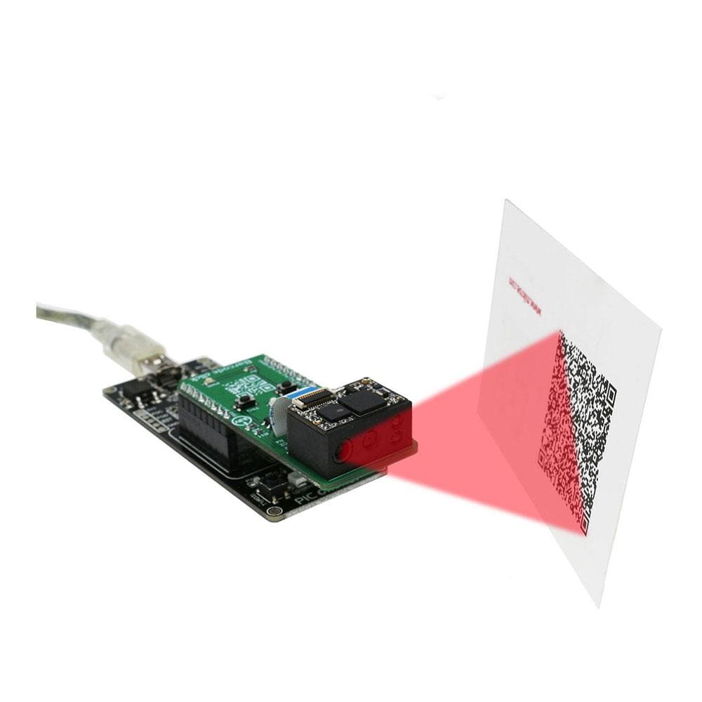
The LV3296, a compact integrated barcode scanner from Rakinda company, is the main component of Barcode Click Board™. This is the advanced barcode scanner/reader module which features the patented UIMG®, a computerized image recognition system technology that supports all mainstream 1D and standard 2D barcode types (for example - PDF417, QR Code M1/M2/Micro and Data Matrix) as well as GS1-DataBar(RSS) (Limited/Stacked/Expanded versions). It can read barcodes on virtually any medium, including paper, plastic, mobile phones, LCD displays, etc. Thanks to the used area-imaging and UIMG® technologies, the device is able to scan barcodes rotated to any angle, with great speed and precision.

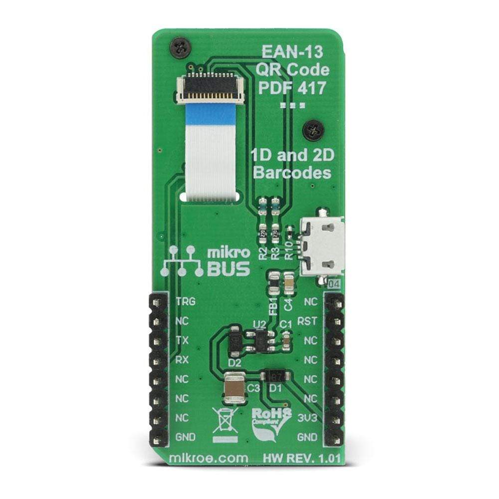
The LV3296 scanner module uses a flat cable to connect to the Click Board™, via the ZIF FPC connector on the back side of the PCB. This flat cable carries all the signals used in communication between the LV3296 module and the host MCU, such as the RX, TX, buzzer, USB, interrupt, reset, and scanning trigger lines.
The communication with Barcode Click Board™ is done by utilising two types of connection it offers - UART (TTL232) and USB. When the Click Board™ is placed into the mikroBUS socket, it will be able to exchange data with the UART module of the MCU, via the standard mikroBUS RX and TX pins.
When the USB cable is connected to the micro USB port on the Click Board™ itself, it can be identified either as the virtual USB port, a HID keyboard device or an HID POS device. HID devices do not require any special PC drivers, while the virtual USB device does.
Many options and parameters of the Barcode Click Board™ are configurable. Barcode Click Board™ configuration is very easy and intuitive - it is enough to read special configuration messages, encoded into barcodes that can be found in the LV3296 user's guide. It is not even necessary to print them on paper - it is enough to show them on screen and scan them from there. Enter Setup message should be scanned first, followed by the desired configuration message. After successful configuration indicated by a short beep sound, the Exit Setup message should be scanned. The device features a very extensive set of encoded configuration commands, which include storing and recal of user default values, along with the factory defaults.
When the Barcode device is first powered up, it will sound a greeting message, which indicates the successful initialization. The device is now ready to scan. Pressing the onboard TRIG button or pulling the PWM pin of the mikroBUS slot to a LOW logic level for at least 10ms, will trigger the barcode scan. It will turn on two LEDs and project a circle shaped aiming pattern on the surface it is aimed at, scanning it for a valid barcode. Both LEDs and the aiming pattern can be turned off in the configuration. A short beep sound and a blink of the Good Read indication onboard LED (GR) will indicate a successful barcode decoding and after releasing the TRIG line (configurable), the device will send the decoded information to the selected interface. Barcode Click Board™ can report errors, with a distinctive error message sound - e.g. when the device is configured to use onboard micro USB, but it is not connected to the host USB device, it will sound an error if scanning is attempted.
The RST button is used to reset the device. Pressing the RST button or pulling the RST line, routed to the mikroBUS RST pin to a LOW logic level for 100us to 500us will cause a device reset, followed by the greeting message sound. It should be noted that the device should not be reset too frequently; at least 2 seconds delay should exist between the reset cycles.
Note: Barcode Click Board™ is powered only with 3.3V from the mikroBUS thus it is not able to work with the MCUs and systems which work on 5V.
SPECIFICATIONS
| Type | Miscellaneous |
| Applications | An ideal solution for fast and accurate scanning of various types of barcodes. |
| On-board modules | LV3296 made by Rakinda company, a compact barcode scanner module armed with the Rakinda patented UIMG® technology |
| Key Features | Fast and accurate scanning of a wide range of 2D and 3D bar code types, can work in a standalone mode via the mikroUSB connector, integrated aim and illumination LEDs |
| Interface | UART,USB |
| Compatibility | mikroBUS |
| Click Board™ size | L (57.15 x 25.4 mm) |
| Input Voltage | 3.3V |
PINOUT DIAGRAM
This table shows how the pinout on Barcode Click Board™ corresponds to the pinout on the mikroBUS socket (the latter shown in the two middle columns).
| Notes | Pin |  |
Pin | Notes | |||
|---|---|---|---|---|---|---|---|
| NC | 1 | AN | PWM | 16 | TRG | Scanning trigger | |
| Reset for LV3296 | RST | 2 | RST | INT | 15 | NC | |
| NC | 3 | CS | RX | 14 | RX | UART data receive | |
| NC | 4 | SCK | TX | 13 | TX | UART data transmit | |
| NC | 5 | MISO | SCL | 12 | NC | ||
| NC | 6 | MOSI | SDA | 11 | NC | ||
| Power supply | 3V3 | 7 | 3.3V | 5V | 10 | NC | |
| Ground | GND | 8 | GND | GND | 9 | GND | Ground |
ONBOARD SETTINGS AND INDICATORS
| Label | Name | Default | Description |
|---|---|---|---|
| PWR | PWR | - | Power LED indicator |
| GR | GR | - | LED indicating a good read |
| General Information | |
|---|---|
Part Number (SKU) |
MIKROE-2913
|
Manufacturer |
|
| Physical and Mechanical | |
Weight |
0.026 kg
|
| Other | |
Country of Origin |
|
HS Code Customs Tariff code
|
|
EAN |
8606018712427
|
Warranty |
|
Frequently Asked Questions
Have a Question?
Be the first to ask a question about this.

