


Mikroelektronika d.o.o.
Brushless 7 Click Board™
Brushless 7 Click Board™
SKU: MIKROE-4182
Couldn't load pickup availability
Overview
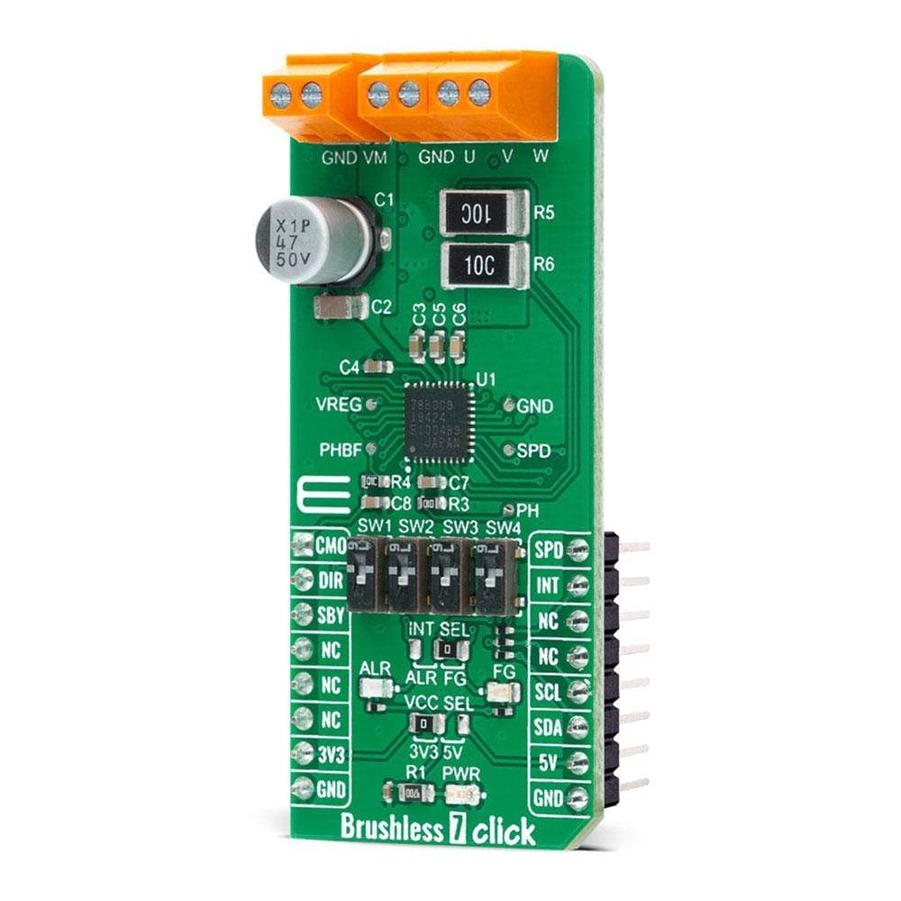
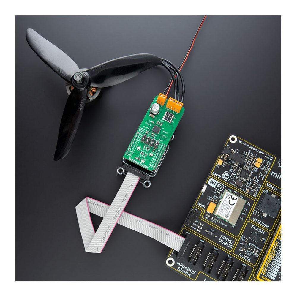
The Brushless 7 Click Board™ is, as its name said, a motor driver based expansion board for controlling BLCD motors with any microcontroller. The board is based on TC78B009FTG IC from Toshiba, which is a three-phase BLDC motor controller that does not require Hall sensors.
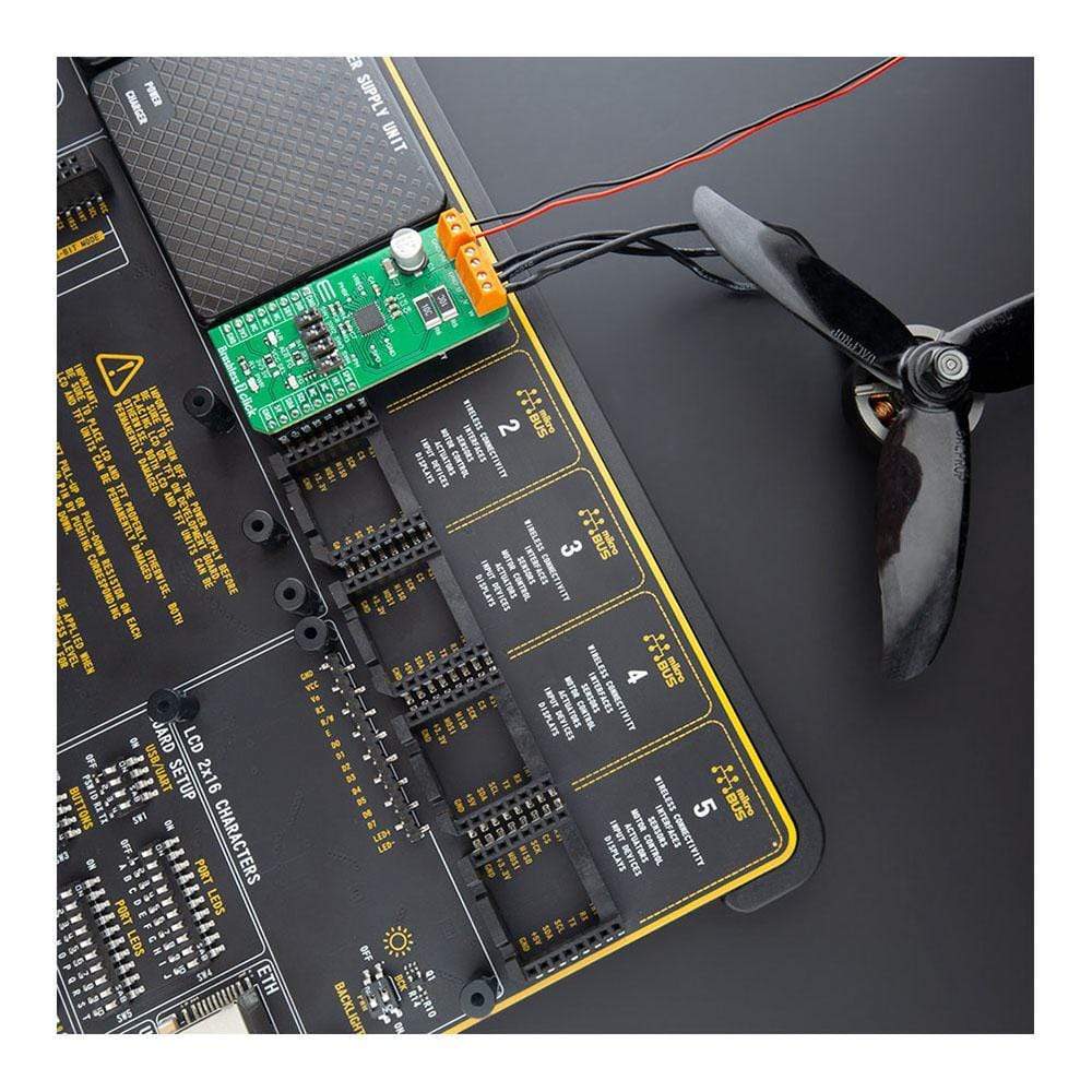
Some of the main features are a built-in closed-loop speed control function that regulates and maintains the motor rotational speed under dynamic power fluctuations and load variations. With the precise setting of a speed profile done by the built-in nonvolatile memory (NVM), it eliminates the need for an external MCU for closed-loop speed control and makes it the perfect solution for applications that include high-speed fans used in servers, blowers, cordless vacuum cleaners, and robot vacuum cleaners.
Downloads
How Does The Brushless 7 Click Board™ Work?
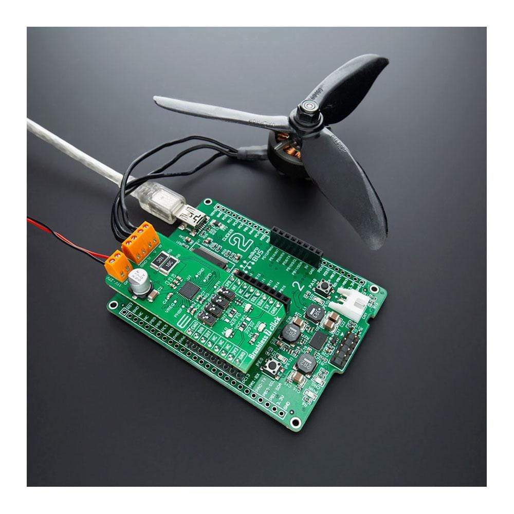
The Brushless 7 Click Board™ is the motor control expansion board based on TC78B009FTG IC which is a three phase PWM chopper driver for sensorless brushless motors and its capable for driving Delta or Wye configured motors. For controlling the motor speed, you can select between couple of interfaces such as PWM duty cycle, I2C or analogue voltage.
One of the biggest advantages of this board is capability to independently monitor and control the motor without an external microcontroller. For doing that the TC78B009FTG features implemented Non-volatile memory (NVM) which serves for storing parameters/modes which will be accessed by the driver and used for control. Operating modes:
- Standby mode – Which can be controlled (ON/OFF setting) by the SBY pin on the mikroBUS, together with register settings
- Brake mode – Period as well as external FET state settings of Brake sequence are set by the register in NVM. Or with the SW1 (BRAKE) switch on the Click board
- Idle mode – Is controlled with the speed commands settings and Error mode
- Error mode - When the abnormality state is detected, the IC enters to the error mode. With visual indication on ALERT LED as well as on INT pin (optional).
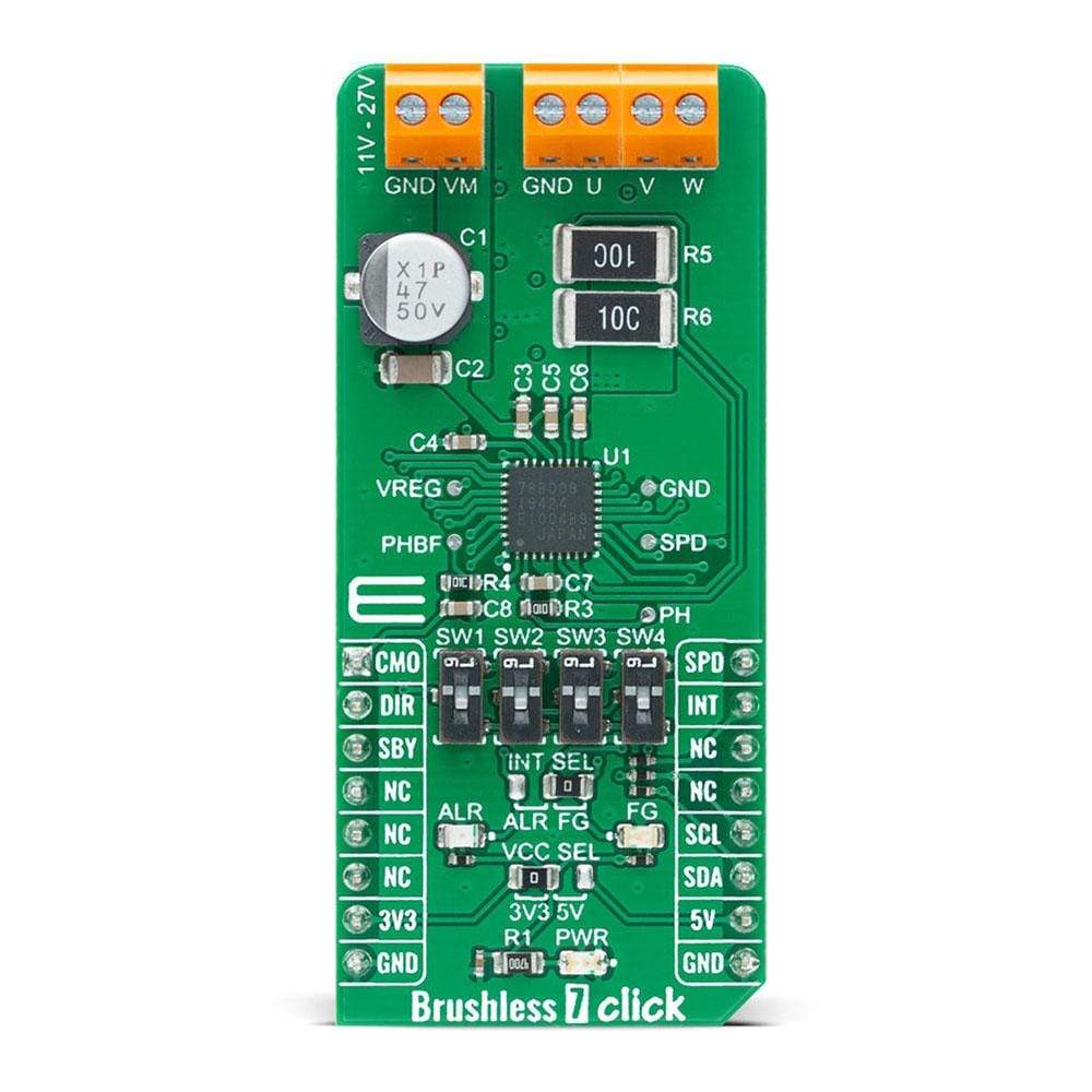
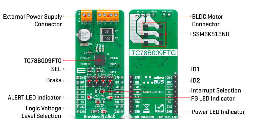
The Brushless 7 Click Board™ also features two SSM6K513NU N-Chanel FETs from Toshiba for each of three phases. Using this FET capable of handling 15A allows low power dissipation when driving 5A BLDC before hitting output current limit threshold. Output current limit function is used to restrain the current flowing to the motor. Motor current is detected by external shunt resistor and the detected voltage is inputted to RSA pin. Minimum and maximum input voltage range must be in range of 11V up to 27V and maximum motor current should not exceed 5A.
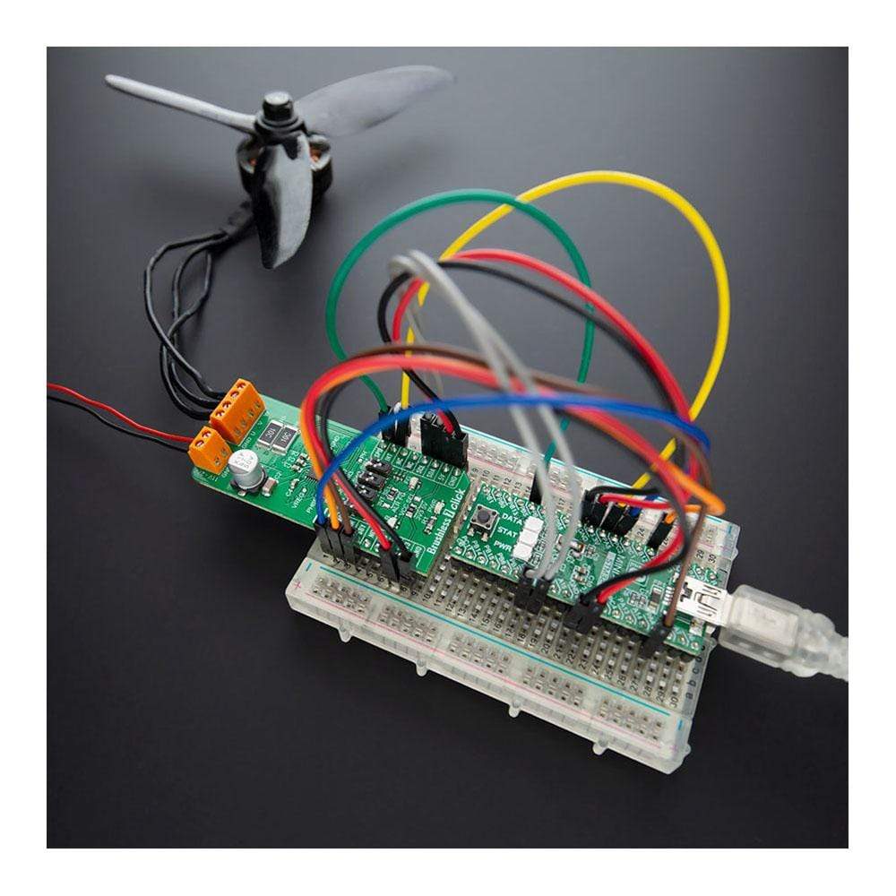
For interfacing to the Brushless 7 Click Board™ you can use I2C interface for various settings over which you can use for setting NVM memory and control the driver, or SPD input pin for controlling the motor speed based on PWM duty cycle or analogue output from the MCU (for this MCU need DAC on the SPD pin of the mikroBUS). The motor's output current can be monitored on the analog output (CMO pin) on mikroBUS™, by amplifying the RSB pin voltage detected by the external shunt resistor and converting it to a DC level with peak hold circuit.
In order to provide additional settings beside interface control for this board, we have used four switches for mode, control and I2C address selection (BRAKE, SEL, ID1 and ID2). This board also has visual indicators for rotation speed (FG LED) and abnormality (ALERT LED) detection monitoring. These indicator statuses can be also visible on INT pin by moving INT SEL jumper to preferred output selection.
SPECIFICATIONS
| Type | Brushless |
| Applications | Servers, Blowers, Fans, Cordless vacuum cleaners, Pumps and many more |
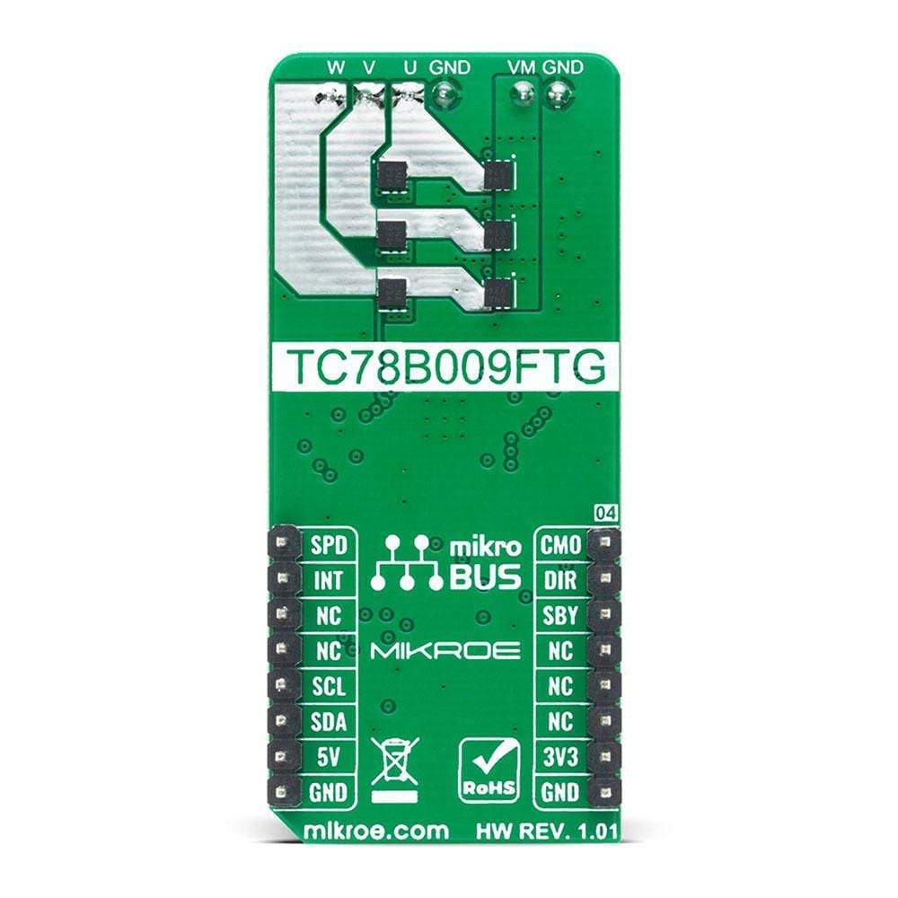
| On-board modules | TC78B009FTG,EL IC from Toshiba is a three-phase BLDC motor controller |
| Key Features | Sensorless PWM drive, Capable to drive Delta or Wye configured motors, Motor speed control by analog voltage, PWM duty cycle, or I2C |
| Interface | GPIO,I2C,PWM |
| Compatibility | mikroBUS |
| Click board size | L (57.15 x 25.4 mm) |
| Input Voltage | 3.3V or 5V |
PINOUT DIAGRAM
This table shows how the pinout on the Brushless 7 Click Board™ corresponds to the pinout on the mikroBUS™ socket (the latter shown in the two middle columns).
| Notes | Pin | Pin | Notes | ||||
|---|---|---|---|---|---|---|---|
| Current Monitor Output | CMO | 1 | AN | PWM | 16 | SPD | Speed Control |
| Rotation Direction | DIR | 2 | RST | INT | 15 | INT | Interrupt |
| Standby | SBY | 3 | CS | RX | 14 | NC | |
| NC | 4 | SCK | TX | 13 | NC | ||
| NC | 5 | MISO | SCL | 12 | SCL | I2C Clock | |
| NC | 6 | MOSI | SDA | 11 | SDA | I2C Data | |
| Power Supply | 3.3V | 7 | 3.3V | 5V | 10 | 5V | Power Supply |
| Ground | GND | 8 | GND | GND | 9 | GND | Ground |
ONBOARD SETTINGS AND INDICATORS
| Label | Name | Default | Description |
|---|---|---|---|
| PWR | LD1 | - | Power LED indicator |
| ALR | LD2 | - | Alert LED indicator |
| FG | LD3 | - | Rotation speed indicator |
| VCC SEL | JP1 | Left | Logic level voltage selection: left position 3V3, right position 5V |
| INT SEL | JP2 | Right | Interrupt selection: left position alert, right position |
| SW1 | BRAKE | UP | Brake input switch: up - VREG, down - GND |
| SW2 | SEL | UP | Selecting speed control switch up - VREG, down - GND |
| SW3 | ID1 | UP | Slave address selection switch up - VREG, down - GND |
| SW4 | ID2 | UP | Slave address selection switch up - VREG, down - GND |
BRUSHLESS 7 CLICK ELECTRICAL SPECIFICATIONS
| Description | Min | Typ | Max | Unit |
|---|---|---|---|---|
| Supply Voltage | 11 | - | 27 | V |
| Output Current | 0 | - | 5 | A |
| VREG | 4.75 | 5 | 5.35 | V |
| General Information | |
|---|---|
Part Number (SKU) |
MIKROE-4182
|
Manufacturer |
|
| Physical and Mechanical | |
Weight |
0.022 kg
|
| Other | |
EAN |
8606027380020
|
Frequently Asked Questions
Have a Question?
Be the first to ask a question about this.