

Mikroelektronika d.o.o.
VCP Monitor Click Board™
VCP Monitor Click Board™
SKU: MIKROE-4039
Couldn't load pickup availability


Overview
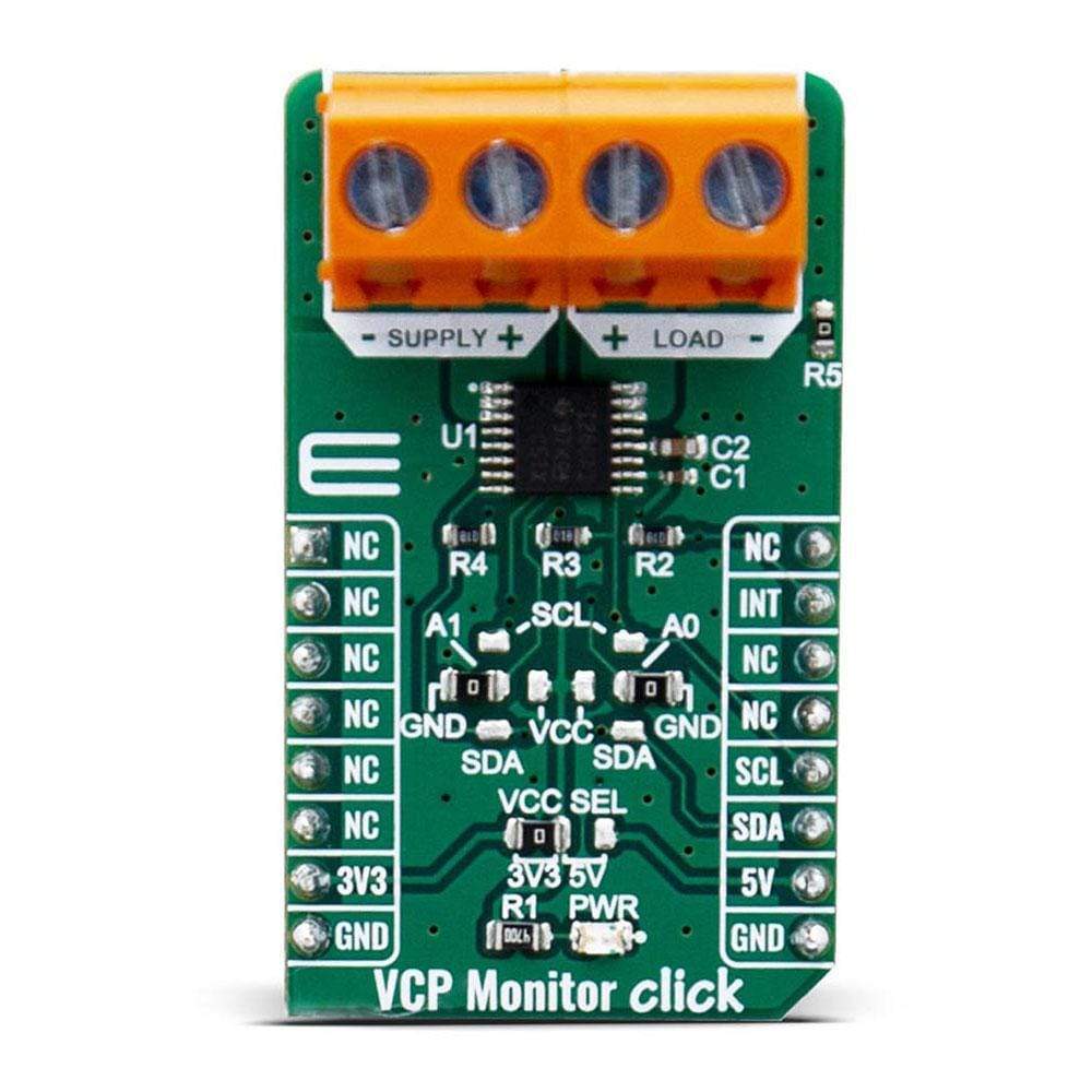
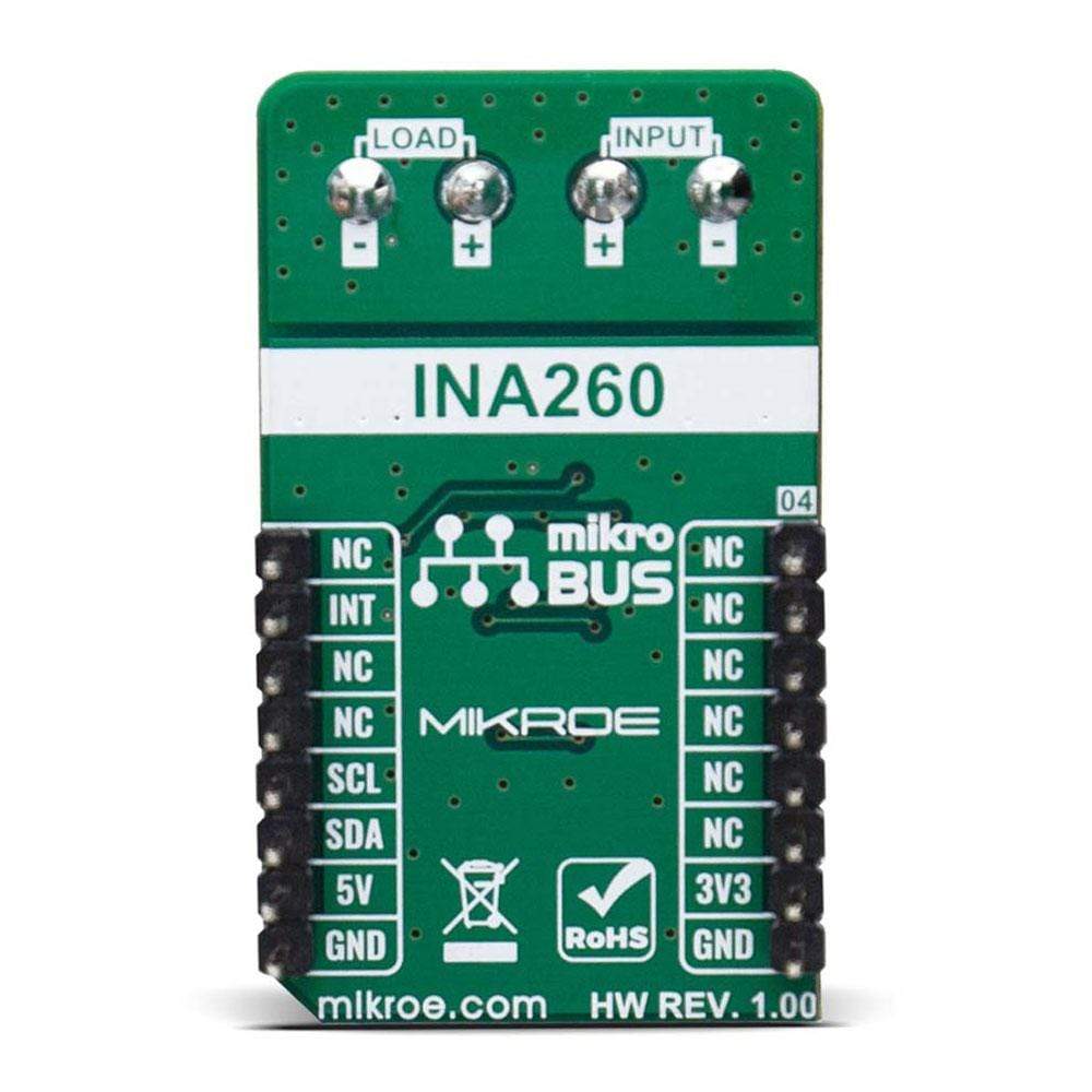
The VCP Monitor Click Board™ is an add-on board power monitor system. This Click Board™ is based on INA260AIPWR - precision digital current and power monitor with low-drift, integrated precision shunt resistor, from Texas Instruments. Therefore, using VCP Monitor Click, current, voltage and power can be monitored. The integrated current-sensing resistor ensures measurement stability over temperature as well as simplifying printed-circuit board layout difficulties common in high precision current sensing measurements.
The VCP Monitor click is supported by a mikroSDK compliant library, which includes functions that simplify software development. This Click Board™ comes as a fully tested product, ready to be used on a system equipped with the mikroBUS™ socket.
Downloads
How Does The VCP Monitor Click Board™ Work?
The VCP Monitor Click Board™ is power monitor system, which includes precision measurement of current, voltage and power with low-drift. The main IC on the VCP Monitor click is INA260AIPWR. The current-sensing resistor is designed as a 4 wire connected resistor that enables accurate measurements through a force-sense connection. The INA260AIPWR is internally calibrated to ensure that the current-sensing resistor and current-sensing amplifier are both precisely matched to one another.
The INA260AIPWR device performs two measurements on power supply bus. The current measurement on LOAD connector, is internally calculated by measuring the voltage developed across a known internal shunt resistor. The features is a physical shunt resistance that is able to withstand current levels higher than the continuous handling limit of 15 A without sustaining damage to the current-sensing resistor or the current-sensing amplifier if the excursions are very brief. The voltage measurement on SUPPLY connector witch is calculated by measuring the voltage from the external VBUS pin to ground. The voltage monitored range from 0V to 36V
The INA260AIPWR device performs two measurements on power supply bus. The current measurement on LOAD connector, is internally calculated by measuring the voltage developed across a known internal shunt resistor, and voltage measurement on SUPPLY connector wich is calculated by measuring the voltage from the external VBUS pin to ground.
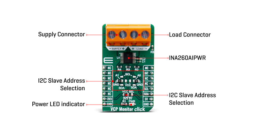
The VCP Monitor click is compatibility with I2C communication protocol. The INA260AIPWR has two slave address selection pins, A0 and A1. For I2C slave address selection, VCP Monitor click has two cross-shape jumpers, first for set pin A0 and second for set A1 pin. One cross-shape jumper has four position for select address pin which can be selected with a SMD 0 ohm resistor, address pin can be connected to GND, VS, SCL or SDA pins. The VCP Monitor click with the two separate jumper on Click board™ user can to set the desired address. The INA260AIPWR provides the opportunity of the 16 possible different I2C addresses.
I2C SLAVE ADDRESS SELECTION
| A1 | A0 | Slave address |
|---|---|---|
| GND | GND | 1000000 |
| GND | VS | 1000001 |
| GND | SDA | 1000010 |
| GND | SCL | 1000011 |
| VS | GND | 1000100 |
| VS | VS | 1000101 |
| VS | SDA | 1000110 |
| VS | SCL | 1000111 |
| SDA | GND | 1001000 |
| SDA | VS | 1001001 |
| SDA | SDA | 1001010 |
| SDA | SCL | 1001011 |
| SCL | GND | 1001100 |
| SCL | VS | 1001101 |
| SCL | SDA | 1001110 |
| SCL | SCL | 1001111 |
The INA260AIPWR is supported with ALERT pin, which is connected to the INT pin on mikroBUS™, in order to interrupt the ongoing MCU routine in case of the alert condition. INT pin can be programmed to respond to a user-defined event or to a conversion ready notification.
The voltage level of the logic section can be selected via VCC SEL jumper, between 3.3V and 5V. This allows for both 3.3V and 5V capable MCUs to use the I2C communication lines properly.
SPECIFICATIONS
| Type | Current sensor |
| Applications | VCP Monitor click click is a perfect solution for the development of the Power Managment system, Battery Chargers and Power Supplies. |
| On-board modules | NA260AIPWR, a digital-output, current, power, and voltage monitor with an I2C and SMBus™-compatible interfacefrom Texas Instruments |
| Key Features | Current Sense Resistance: 2 mΩ, Tolerance Equivalent to 0.1%, 15-A Continuous From –40°C to +85°C, 16 Programmable Addresses. |
| Interface | I2C |
| Compatibility | mikroBUS |
| Click board size | M (42.9 x 25.4 mm) |
| Input Voltage | 3.3V or 5V |
PINOUT DIAGRAM
This table shows how the pinout on VCP Monitor click corresponds to the pinout on the mikroBUS™ socket (the latter shown in the two middle columns).
| Notes | Pin | Pin | Notes | ||||
|---|---|---|---|---|---|---|---|
| NC | 1 | AN | PWM | 16 | NC | ||
| NC | 2 | RST | INT | 15 | INT | Interrupt OUT | |
| NC | 3 | CS | RX | 14 | NC | ||
| NC | 4 | SCK | TX | 13 | NC | ||
| NC | 5 | MISO | SCL | 12 | SCL | I2C Clock | |
| NC | 6 | MOSI | SDA | 11 | SDA | I2C Data | |
| Power Supply | 3.3V | 7 | 3.3V | 5V | 10 | 5V | Power supply |
| Ground | GND | 8 | GND | GND | 9 | GND | Ground |
ONBOARD SETTINGS AND INDICATORS
| Label | Name | Default | Description |
|---|---|---|---|
| PWR | PWR | - | Power LED Indicator |
| JP1 | VCC SEL | Left | Power supply voltage selection 3v3/5v: left position 3v3, right position 5v |
| JP2,JP3 | ADD A0 | Left | 4-position I2C address Selection toward host mcu: left - GND; Right - VCC; Up - SCL; Down - SDA |
| JP4,JP5 | ADD A1 | Right | 4-position I2C address Selection toward host mcu: left - GND; Right - VCC; Up - SCL; Down - SDA |
VCP MONITOR CLICK ELECTRICAL SPECIFICATIONS
| Description | Min | Typ | Max | Unit |
|---|---|---|---|---|
| Input voltage (SUPPLY terminal) | 0 | 36 | V | |
| Out voltage (LOAD terminal) | 0 | 36 | V | |
| OUT Current (LOAD terminal) | -15 | 15 | A |
| General Information | |
|---|---|
Part Number (SKU) |
MIKROE-4039
|
Manufacturer |
|
| Physical and Mechanical | |
Weight |
0.022 kg
|
| Other | |
EAN |
8606018718078
|
Frequently Asked Questions
Have a Question?
Be the first to ask a question about this.