


Mikroelektronika d.o.o.
Spectral 2 Click Board™
Spectral 2 Click Board™
SKU: MIKROE-2973
Couldn't load pickup availability

Overview
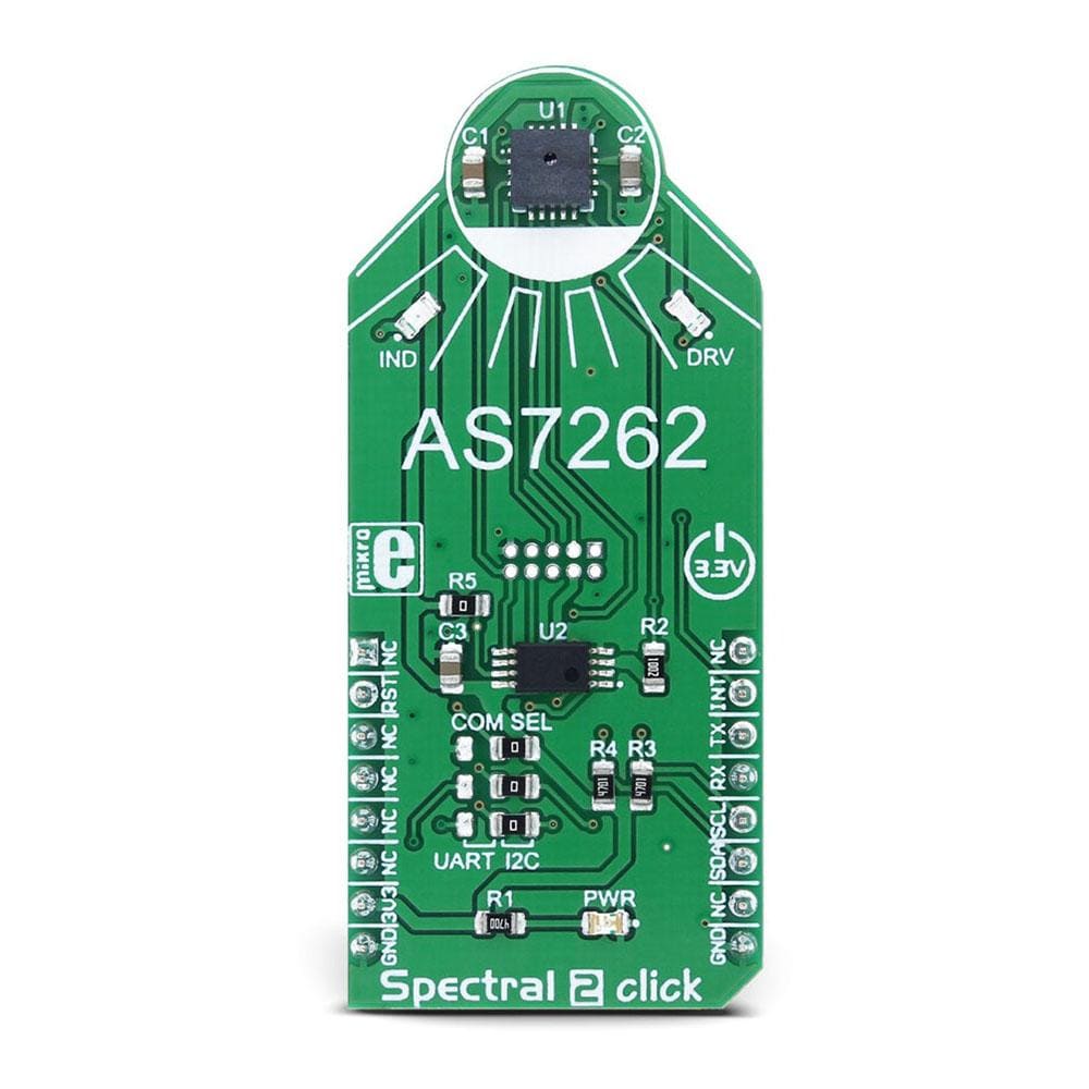
The Spectral 2 Click Board™ is a multispectral colour sensing device, which uses the state-of-the-art sensor IC for very accurate colour sensing. The sensor on the Spectral 2 Click Board™ provides multi-spectral sensing in the visible range of wavelengths from approximately 430nm to 670nm with the full width at half maximum (FWHM) of 40nm.
The Spectral 2 Click Board™ provides a direct reading of the six different colour components with the 16-bit precision, as well as the calibrated reading, that gives 32-bit float values with an 8-bit biased exponent and a 23bit fraction part, processed through the Spectral ID engine. The sensor also integrates two programmable LED channels with constant current drivers, useful for indication and for providing the backlight for the measured colour object.
.
Downloads
The Spectral 2 Click Board™ is a multispectral colour sensing device, which uses the state-of-the-art sensor IC for very accurate colour sensing. The sensor on the Spectral 2 click provides multi-spectral sensing in the visible range of wavelengths from approximately 430nm to 670nm with the full width at half maximum (FWHM) of 40nm. The Spectral 2 Click Board™ provides a direct reading of the six different colour components with the 16bit precision, as well as the calibrated reading, that gives 32bit float values with an 8bit biased exponent and a 23bit fraction part, processed through the Spectral ID engine. The sensor also integrates two programmable LED channels with constant current drivers, useful for indication and for providing the backlight for the measured colour object.
The onboard sensor has minimal drift over time and with temperature, which makes it very reliable, even after long periods of time. The integrated temperature sensor compensates for all the thermal influences from the environment. Equipped with such an advanced multispectral sensor IC, the Spectral 2 Click Board™ can be used in various spectrometry applications, used for colour measurement, spectral identification, colour matching, colour tuning and calibration, even for counterfeit detection based on the slight colour mismatching. Essentially – for any professional-grade applications that require a high degree of colour recognition accuracy and consistency.
How Does The Spectral 2 Click Board™ Work?
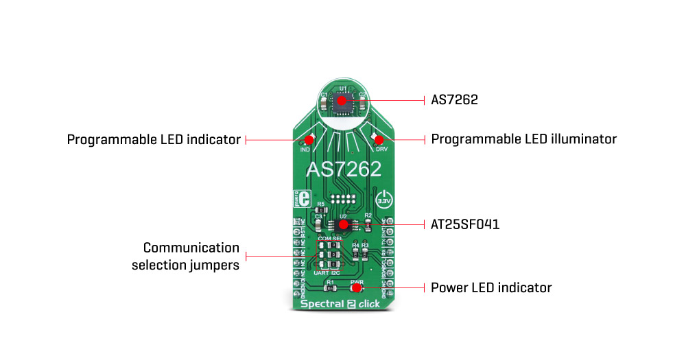
The multispectral sensor IC used on the Spectral 2 Click Board™ is the AS7262, 6 channel visible spectral_ID device with an electronic shutter and smart Interface. This is a very advanced multispectral sensor, which incorporates a 6 photodiodes array element. Every photo element is filtered through the Gaussian filters, implemented through the nano-optics deposited interference filter technology, designed to provide ranges for 6 visible channels: 450nm, 500nm, 550nm, 570nm, 600nm and 650nm, each with 40nm FWHM. The filter characteristics are tested and measured with the 5700K white LED light. This technology ensures minimal drift of the readings and temperature stability. It should be noted that the filter accuracy will be affected by the angle of incidence, determined by an integrated aperture and the internal microlenses, which is ±20° for the AS7262 IC.
The measurements from the photo elements are digitized by the 16bit ADC converter and processed by the spectral_ID engine. Besides the raw values of the six colour elements, which can be read from the registers as 16bit integer values, the engine calculates all the calibrated values available on this device and outputs them as 32bit float values with an 8bit biased exponent and a 23bit fraction part. After the specified integration time, those values are available in their respective registers and are accessible via the smart high-level UART interface driven by simple AT commands, or the I2C communication protocol bus. Even the temperature sensor can be accessed via its register. A complete list of all the available color coordinates and the registers which hold these values can be found in the AS7262 datasheet.
The sensor data is organized in two banks. The first bank contains readings from the V, B, G and Y photodiodes, while the second bank contains readings from the G, Y, O and R photodiodes. Different modes allow readings to be made from each bank, as well as the combinations between these two banks. There is also a mode for one-shot reading when time-critical or triggered measurement needs to be made. The photodiode letter codes above represent the colours of the respective wavelengths (Violet, Blue, Green, Yellow, Orange, and Red)
An interrupt can be triggered when the data is ready to be read by the host, depending on the selected bank mode. If the interrupt is enabled (INT = 1), the INT line is pulled to a LOW logic level and DATA_RDY bit of the control register is set to 1. The INT line is released when the control register is read. The DATA_RDY bit will be cleared whenever the measurement registers are read. The interrupt will be generated after one or more integrating cycles are completed, depending on the selected bank mode. The INT line of the AS7262 is routed to the mikroBUS™ INT pin and can be used to trigger an interrupt on the host MCU. More about bank reading modes and the interrupts can be found in the provided AS7262 datasheet.
The RESET line of the sensor is routed to the mikroBUS™ RST pin. If this line is pulled to a LOW level for more than 100ms, it will reset the device.
The sensor firmware is kept externally, on the auxiliary flash memory IC. The AT25SF041, an SPI serial flash memory is used for storing the firmware of the AS7262 sensor. The AT25SF041 IC communicates with the sensor via the SPI lines, internally routed on the Spectral 2 click.
UART and I2C lines of the AS7262 sensor are routed to the mikroBUS™ respective UART pins (RX/TX and SDA/SCL). To select which interface will be used to drive the sensor IC, three onboard SMD jumpers labelled as COM SEL need to be moved either to the left position (to enable UART), or to the right position (to enable I2C). It should be noted that all the SMD jumpers need to be moved at once - if some of them are set as UART and some as I2C, the communication might not be possible at all.
There are two integrated programmable LED drivers on the AS7262 sensor. The first LED constant current driver can be programmed up to 10mA and it can be used as the status indicator. It is also activated during the sensor firmware programming. The second LED driver is intended for driving the light source for the measurement surface illumination. It can drive high brightness LEDs with up to 100mA. Both of these LED drivers are available through communication interfaces.
SPECIFICATIONS
| Type | Optical |
| Applications | Portable spectrometry applications, color matching and identification, precision color tuning/calibration, and similar applications that rely on reliable and precise color sensing |
| On-board modules | AS7262, a digital 6-channel spectrometer for spectral identification in the visible light wavelength range, with electronic shutter and smart interface, from ams; AT25SF041, a 4Mb SPI serial flash from Adesto Technologies |
| Key Features | Compact 6-channel visible spectrum solution realized by the proprietary silicon interference filters, lifetime-calibrated sensing with no drift over time or temperature, on-chip data processing, auxiliary illumination LED drivers, smart UART interface |
| Interface | I2C,UART |
| Compatibility | mikroBUS |
| Click board size | L (57.15 x 25.4 mm) |
| Input Voltage | 3.3V |
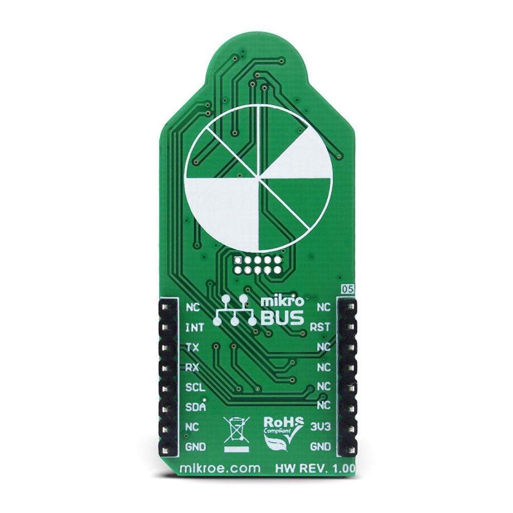
PINOUT DIAGRAM
This table shows how the pinout on Spectral 2 Click Board™ corresponds to the pinout on the mikroBUS™ socket (the latter shown in the two middle columns).
| Notes | Pin | Pin | Notes | ||||
|---|---|---|---|---|---|---|---|
| NC | 1 | AN | PWM | 16 | NC | ||
| Reset | RST | 2 | RST | INT | 15 | INT | Interrupt |
| NC | 3 | CS | RX | 14 | TX | UART transmit | |
| NC | 4 | SCK | TX | 13 | RX | UART receive | |
| NC | 5 | MISO | SCL | 12 | SCL | I2C Clock | |
| NC | 6 | MOSI | SDA | 11 | SDA | I2C Data | |
| Power supply | +3.3V | 7 | 3.3V | 5V | 10 | NC | |
| Ground | GND | 8 | GND | GND | 9 | GND | Ground |
ONBOARD SETTINGS AND INDICATORS
| Label | Name | Default | Description |
|---|---|---|---|
| LD1 | PWR | - | Power LED indicator |
| LD2 | IND | - | Programmable constant current LED indicator |
| LD3 | DRV | - | Programmable constant current LED illuminator |
| JP1 | COM.SELL. | Right | Communication Interface Selection I2C/UART, left position UART, right position I2C |
| JP2 | COM.SELL. | Right | Communication Interface Selection I2C/UART, left position UART, right position I2C |
| JP3 | COM.SELL. | Right | Communication Interface Selection I2C/UART, left position UART, right position I2C |
| General Information | |
|---|---|
Part Number (SKU) |
MIKROE-2973
|
Manufacturer |
|
| Physical and Mechanical | |
Weight |
0.019 kg
|
| Other | |
EAN |
8606018712717
|
Frequently Asked Questions
Have a Question?
Be the first to ask a question about this.