


SEGGER Microcontroller GmbH
SEGGER Flasher ATE Main Module
SEGGER Flasher ATE Main Module
SKU: 5.18.01
Couldn't load pickup availability
Key Features
Overview
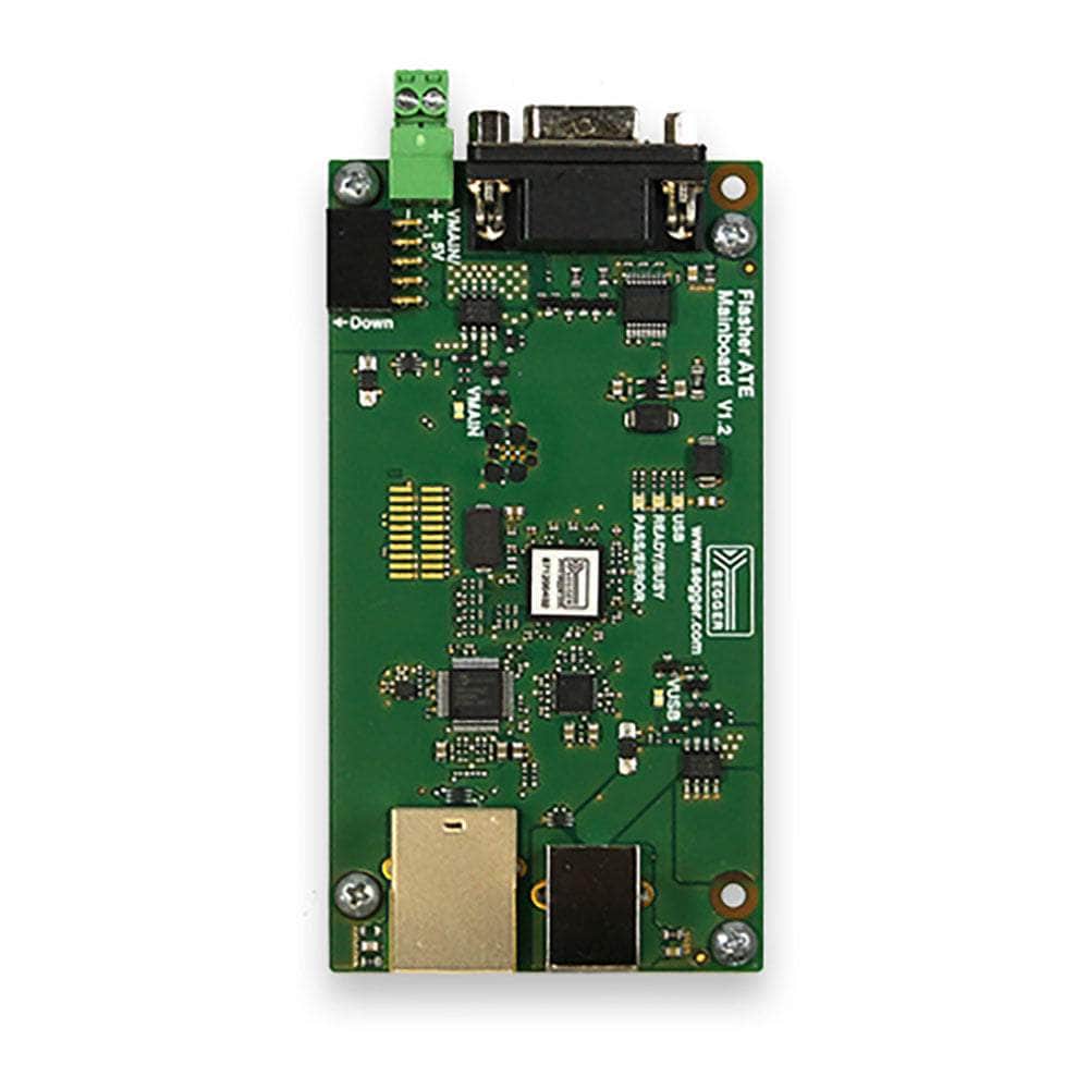
The SEGGER Flasher ATE Main Module serves as the central communication hub for high-volume automated flash programming operations. This modular mainboard coordinates commands between automated test equipment (ATE) systems and up to 10 individual programming modules, enabling simultaneous programming of multiple target devices with proven SEGGER flash algorithms.
Built for industrial production environments, the main module features multiple communication interfaces including Ethernet (10/100 Mbit), USB 2.0, and RS232, allowing seamless integration into existing production workflows. Each programming operation utilises the same market-leading algorithms found in SEGGER J-Link debug probes and Flasher programming devices.
The system supports both remote-controlled operation via PC commands and standalone handshake mode for direct ATE integration. With 128MB memory per module and integrated FTP/web servers, configuration management and monitoring become straightforward in production environments. Compatible with ARM Cortex, AVR, MSP430, PIC, RL78, RX, STM8 and other major microcontroller families through various programming adapters.
Downloads
Why Engineers Choose The SEGGER Flasher ATE Main Module
Production Scalability
ATE Integration
Proven Reliability
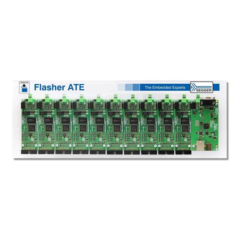
System Architecture and Scalability
The SEGGER Flasher ATE Main Module forms the central communications hub in a modular high-volume flash programming system. As the mainboard controller, it manages command distribution between host ATE systems and up to 10 individual programming modules via an internal bus architecture. This modular approach enables unprecedented scalability in production environments, allowing manufacturers to configure systems from single-module prototyping setups to full 10-module high-throughput production lines.
Each programming module operates independently with its own 128MB memory storage, programming circuit, and target interface. The Main Module coordinates these resources whilst maintaining functional isolation between programming channels, preventing cross-contamination and enabling simultaneous programming of different target types or firmware versions.
Communication Interfaces and ATE Integration
The Main Module provides comprehensive connectivity options for diverse production environments. The primary interfaces include:
| Interface | Specification | Use Case |
|---|---|---|
| Ethernet | 10/100 Mbit | Remote control, FTP access, web monitoring |
| USB 2.0 | High-Speed | PC configuration, firmware updates |
| RS232 | 9-pin | ATE handshake control, ASCII commands |
The RS232 interface supports both simple 3-wire handshake control for basic ATE integration and full ASCII command protocol for advanced remote control with detailed status reporting.
Target Interface Support and Programming Capabilities
Programming modules connect to targets via standard 20-pin JTAG/SWD connectors with support for various interface types through optional adapters. The system utilises the same proven flash algorithms found in SEGGER's J-Link debug probes, ensuring reliable programming across diverse microcontroller families.
Supported Programming Interfaces
- JTAG: IEEE 1149.1 standard, up to 15 MHz clock frequency
- SWD: ARM Serial Wire Debug protocol
- SWIM: STM8 Single Wire Interface Module
- PDI: Atmel Program and Debug Interface
- ICSP: In-Circuit Serial Programming for PIC devices
- SPI: Serial Peripheral Interface for external flash
Power Supply and Environmental Specifications
| Parameter | Specification | Notes |
|---|---|---|
| Supply Voltage | 4.8 - 5.25V DC | Via VMAIN connector or USB |
| Power Consumption | Max 3A (10 modules) | 100mA mainboard + 220mA per module |
| Operating Temperature | +5°C to +60°C | Industrial production environment |
| Storage Temperature | -20°C to +65°C | Non-condensing humidity <90% RH |
| Dimensions | 108 × 56 × 20mm | Mainboard without cables |
| Weight | 47g | Mainboard only |
Memory Storage and File Management
Each programming module incorporates 128MB of non-volatile memory for storing configuration files, firmware images, and programming data. The integrated FTP server provides network-based file access, with each module appearing as a separate directory (Module.001 through Module.010) in the file system hierarchy.
// Example FTP directory structure / ├── Module.001/ │ ├── firmware.dat │ ├── config.cfg │ └── project.pex ├── Module.002/ │ ├── bootloader.dat │ └── config.cfg └── Module.010/ ├── application.dat └── config.cfg File transfers support both standard firmware formats (Intel HEX, Motorola S-Record, binary) and SEGGER's native .DAT format for optimal programming performance.
Operating Modes and Control Methods
Remote-Controlled Mode
In remote-controlled mode, the Main Module receives commands via Ethernet, USB, or RS232 ASCII interface. This mode provides comprehensive status reporting, error diagnostics, and programming verification, making it ideal for automated production lines requiring detailed process monitoring.
Handshake Mode
Handshake mode enables direct ATE integration through simple digital I/O signals via the RS232 connector. Programming operations are triggered by hardware signals without requiring host PC interaction, streamlining integration into existing production equipment.
Setup and Configuration Workflow
Initial system configuration utilises J-Flash software to create project files containing target-specific programming parameters. These configuration (.CFG) and data (.DAT) files are then uploaded to individual modules via FTP, enabling autonomous operation without ongoing PC connectivity.
- Project Creation: Use J-Flash to configure target device, memory layout, and programming options
- File Generation: Export configuration and firmware files in SEGGER format
- FTP Upload: Transfer files to appropriate module directories via network connection
- Module Selection: Configure FLASHER.ini files to specify active project per module
- Verification: Test programming operations before production deployment
Serial Number Programming and Traceability
The system supports automatic serial number programming for production traceability requirements. Serial numbers can be programmed as continuous sequences, from predefined lists, or with custom patch data applied per programming cycle. This capability ensures unique device identification whilst maintaining high-throughput programming speeds.
Web Interface and Remote Monitoring
The integrated web server provides browser-based access to system status, configuration parameters, and operational statistics. Production managers can monitor programming progress, view error logs, and adjust system parameters remotely without specialised software installation.
| Web Interface Feature | Functionality |
|---|---|
| System Overview | Module status, programming progress, error indicators |
| Network Configuration | IP settings, DHCP configuration, connectivity status |
| Module Management | Individual module control, firmware versions, memory usage |
| Log Access | Programming logs, error history, statistical reports |
Frequently Asked Questions
Have a Question?
-
Is the Flasher ATE Main Module compatible with existing SEGGER software?
Yes, the system works with J-Flash software for project configuration and the Universal Flash Loader Configurator. Setup files created in J-Flash can be directly uploaded to the modules via FTP for production use.
-
What programming speeds can be achieved with the Flasher ATE system?
Programming speeds reach up to 300 KBytes/second depending on target hardware, interface type, and JTAG clock frequency. The modular approach enables parallel programming to multiply effective throughput.
-
How does the Main Module integrate with existing ATE systems?
Integration occurs through the RS232 handshake interface (pins 1, 4, 5, 7) for simple start/stop control, or via Ethernet/RS232 ASCII command interface for advanced remote control with detailed status reporting and error handling.
-
What power supply options are available for the Main Module?
The Main Module can be powered via USB (for basic operation) or external 5V DC supply via the VMAIN connector (recommended for full 10-module configurations). Maximum power consumption is 3A when using all 10 modules.
-
Can I mix different target types across the programming modules?
Yes, each programming module can be configured independently with different firmware images, configuration files, and target settings, allowing simultaneous programming of various microcontroller types in mixed production scenarios.
-
What communication interfaces are available on the Main Module?
The Main Module provides 10/100 Mbit Ethernet, USB 2.0 High-Speed, and RS232 9-pin interfaces for host communication, plus individual module control via the internal ATE bus system.
-
How do I upload firmware and configuration files to the Main Module?
Files are transferred using the integrated FTP server accessible via Ethernet connection. Each programming module appears as a separate folder (Module.001, Module.002, etc.) where configuration (.CFG) and data (.DAT) files are stored.
-
What microcontroller families are supported by the Flasher ATE system?
The system supports ARM Cortex-M, ARM7/9/11, AVR, MSP430, PowerPC e200z0, PIC, RL78, RX, STM8, and 8051 cores through various programming interfaces including JTAG, SWD, SWIM, PDI, ICSP, and SPI.
-
Can the Flasher ATE Main Module operate without a PC connection?
Yes, the Main Module supports standalone handshake mode where programming is triggered directly by ATE control signals via the RS232 connector. Once configured, it operates autonomously without requiring a host PC connection.
-
What is the difference between the Flasher ATE Main Module and the newer Flasher ATE2?
The Main Module is part of the original modular Flasher ATE system requiring separate programming modules, whilst the ATE2 is a single-board solution with 8 integrated programming channels. The Main Module offers greater scalability (up to 10 modules vs 8 channels) and modular flexibility for custom production setups.