Key Features
Overview
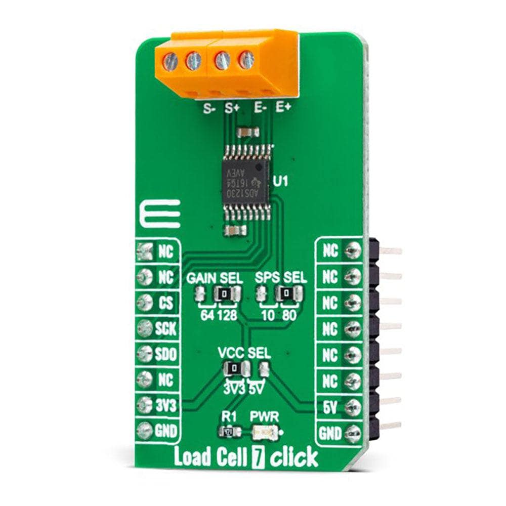
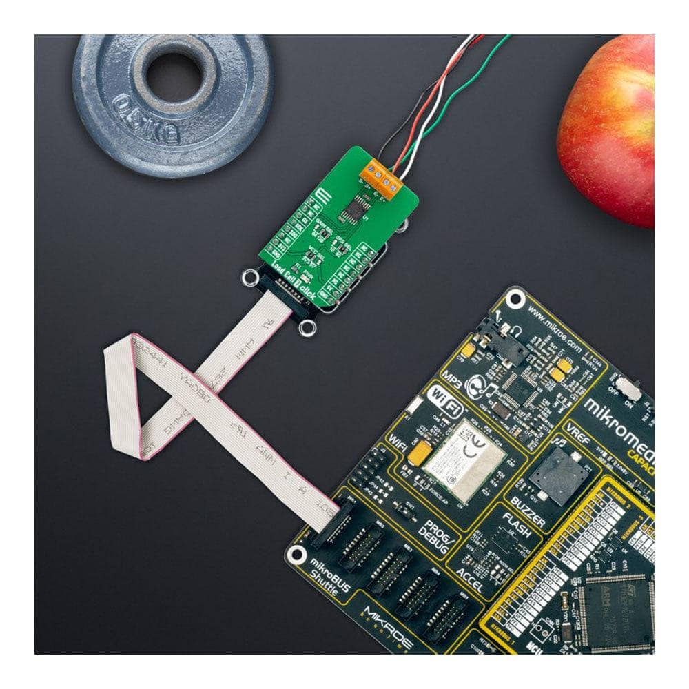
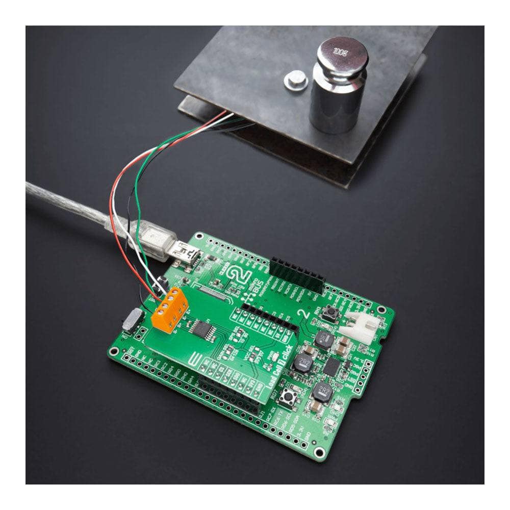
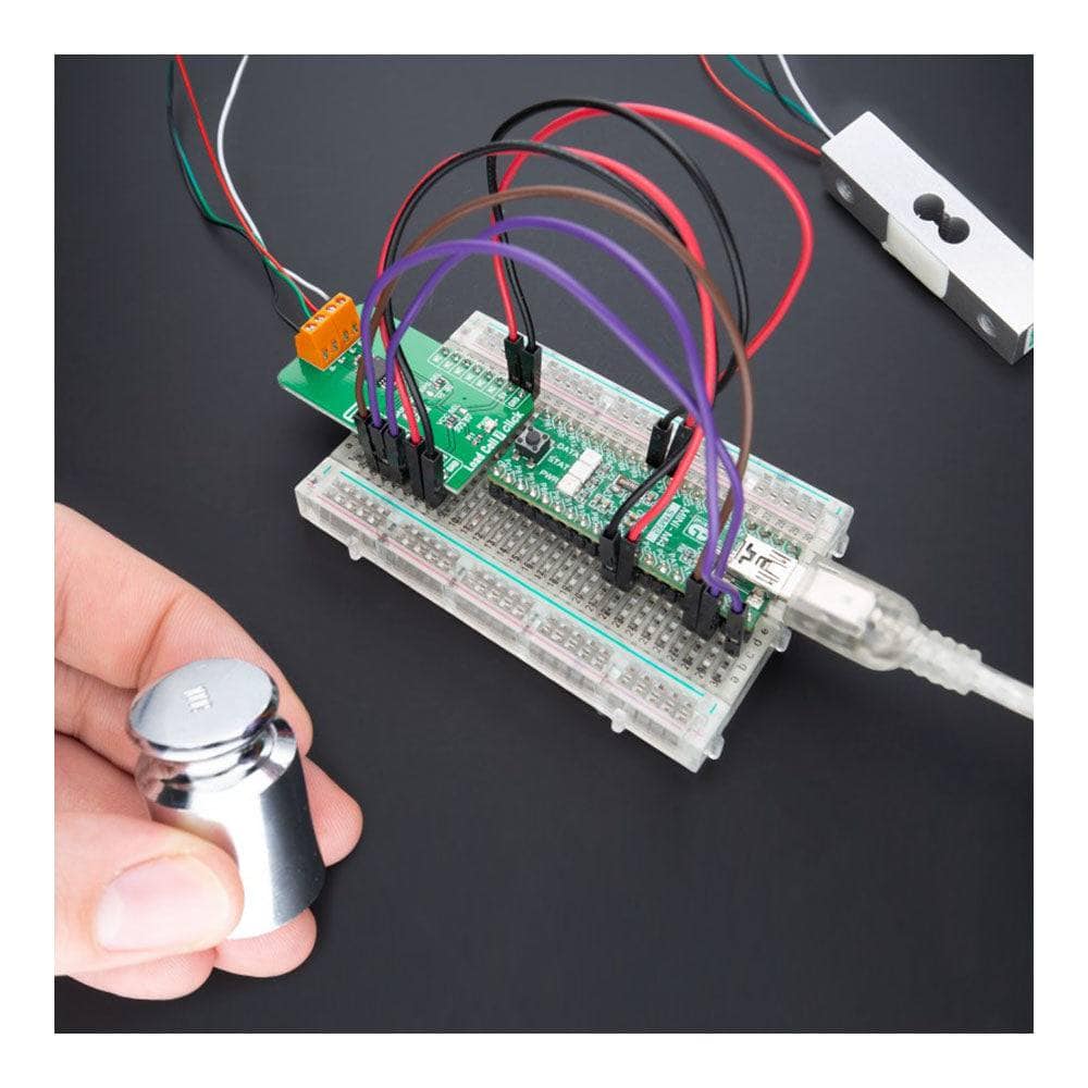
The Load Cell 7 Click Board™ is a compact add-on board representing a weigh scale solution. This board features the ADS1230, a high-precision 20-bit delta-sigma analogue-to-digital converter (ADC) with an outstanding noise performance from Texas Instruments. This SPI-configurable ADC (read-only) offers selectable gain and data rate values, supporting a full-scale differential input of ±39mV/±19.5mV and 10SPS/80SPS, respectively. It comes with an onboard low-noise programmable gain amplifier (PGA) and onboard oscillator providing a complete front-end solution. This Click board™ has many features that make it a perfect fit for bridge sensor applications, including industrial process control, weigh scales, and strain gauges.
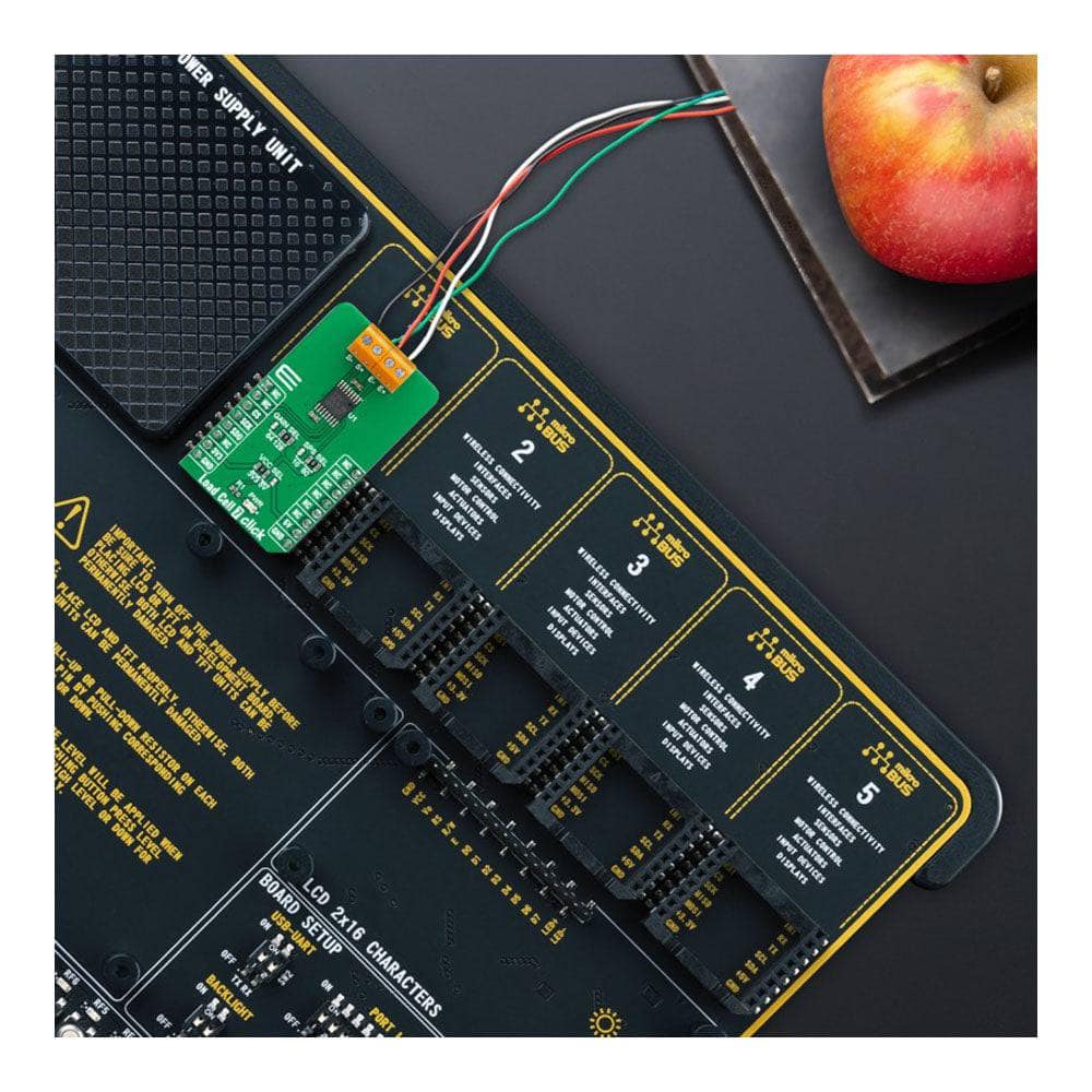
The Load Cell 7 Click Board™ is supported by a mikroSDK compliant library, which includes functions that simplify software development. This Click board™ comes as a thoroughly tested product, ready to be used on a system equipped with the mikroBUS™ socket.
Downloads
How Does The Load Cell 7 Click Board™ Work?
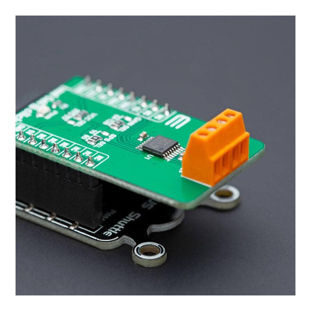
The Load Cell 7 Click Board™ as its foundation uses the ADS1230, a high accuracy, low noise, and low power 20-bit ΣΔ ADC with an outstanding noise performance from Texas Instruments. It includes a low-noise PGA, internal oscillator, third-order delta-sigma (ΔΣ) modulator, and fourth-order digital filter, thus providing a complete front-end solution for bridge sensor applications. The ADS1230 is easy to configure, and all digital control is accomplished through dedicated pins; there are no registers to program. The conversions from the ADS1230 are sent to the MCU through SPI serial interface, with the digital information converted to weight.
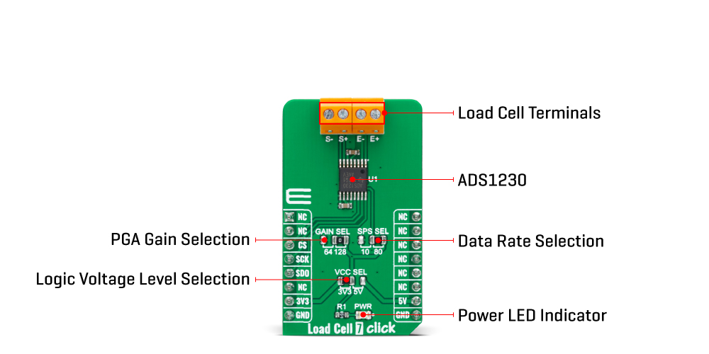
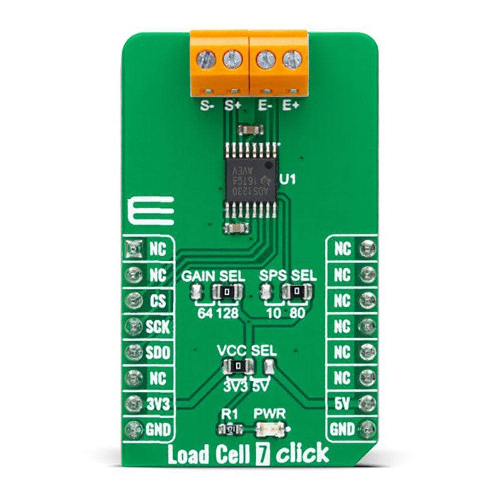
The low-noise PGA has a selectable gain, performed by an onboard SMD jumper labelled as GAIN SEL to an appropriate position marked as 64 and 128, supporting a full-scale differential input of ±39mV or ±19.5mV, respectively. Besides, data can be output at 10SPS for excellent 50Hz and 60Hz rejection or at 80SPS when higher speeds are needed. The onboard SMD jumper labelled SPS SEL can select this feature, placing it in an appropriate position marked as 10 and 80. The ADS1230 can be put in a low-power standby mode or shut off completely in power-down mode.
The Load Cell 7 Click Board™ uses the 4-wire load cell configuration, with two sense pins and two output connections. The load cell differential S lines connected to the AD7780 reference inputs create a ratiometric configuration immune to low-frequency changes in the power supply excitation voltage. Those sense pins are connected to the high and low sides of the Wheatstone bridge, where voltage can be accurately measured, regardless of the voltage drop due to the wiring resistance.
The Load Cell 7 Click Board™ can operate with both 3.3V and 5V logic voltage levels selected via the VCC SEL jumper. This way, it is allowed for both 3.3V and 5V capable MCUs to use the communication lines properly. However, the Click board™ comes equipped with a library containing easy-to-use functions and an example code that can be used, as a reference, for further development.
SPECIFICATIONS
| Type | Force |
| Applications | Can be used for bridge sensor applications, including industrial process control, weigh scales, and strain gauges |
| On-board modules | ADS1230 - 20-bit delta-sigma analog-to-digital converter (ADC) from Texas Instruments |
| Key Features | High precision, outstanding noise performance, selectable gain and data rate, complete front-end for bridge sensor, low power consumption, and more |
| Interface | SPI |
| Compatibility | mikroBUS |
| Click board size | M (42.9 x 25.4 mm) |
| Input Voltage | 3.3V or 5V |
PINOUT DIAGRAM
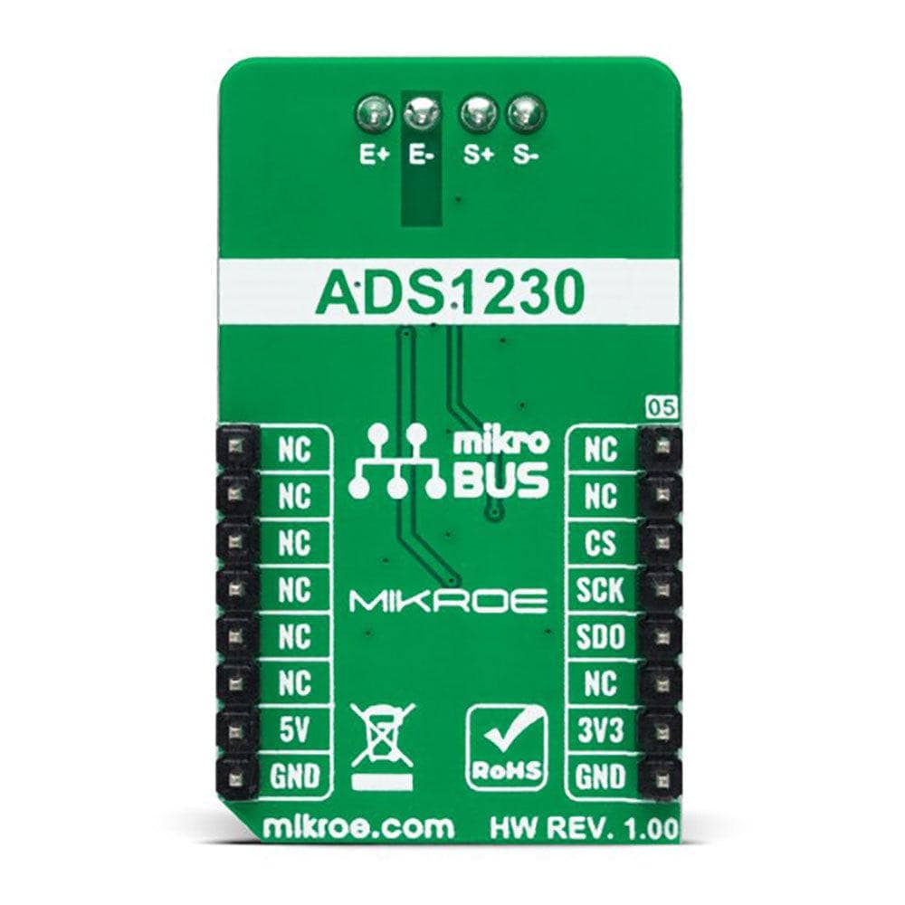
This table shows how the pinout of the Load Cell 7 Click Board™ corresponds to the pinout on the mikroBUS™ socket (the latter shown in the two middle columns).
| Notes | Pin |  |
Pin | Notes | |||
|---|---|---|---|---|---|---|---|
| NC | 1 | AN | PWM | 16 | NC | ||
| NC | 2 | RST | INT | 15 | NC | ||
| SPI Chip Select | CS | 3 | CS | RX | 14 | NC | |
| SPI Clock | SCK | 4 | SCK | TX | 13 | NC | |
| SPI Data OUT | SDO | 5 | MISO | SCL | 12 | NC | |
| NC | 6 | MOSI | SDA | 11 | NC | ||
| Power Supply | 3.3V | 7 | 3.3V | 5V | 10 | 5V | Power Supply |
| Ground | GND | 8 | GND | GND | 9 | GND | Ground |
ONBOARD SETTINGS AND INDICATORS
| Label | Name | Default | Description |
|---|---|---|---|
| LD1 | PWR | - | Power LED Indicator |
| JP1 | VCC SEL | Left | Logic Level Voltage Selection 3V3/5V: Left position 3V3, Right position 5V |
| JP2 | SPS SEL | Right | Data Rate Selection 10/80: Left position 10, Right position 80 |
| JP3 | GAIN SEL | Right | PGA Gain Selection 64/128: Left position 64, Right position 128 |
LOAD CELL 7 CLICK ELECTRICAL SPECIFICATIONS
| Description | Min | Typ | Max | Unit |
|---|---|---|---|---|
| Supply Voltage | 3.3 | - | 5 | V |
| Common-Mode Input Range | 1.5 | - | 3.5 | V |
| Resolution | 20 | - | - | bit |
| Operating Temperature Range | -40 | +25 | +85 | °C |
| General Information | |
|---|---|
Part Number (SKU) |
MIKROE-5276
|
Manufacturer |
|
| Physical and Mechanical | |
Weight |
0.02 kg
|
| Other | |
Country of Origin |
|
HS Code Customs Tariff code
|
|
EAN |
8606027387982
|
Warranty |
|
Frequently Asked Questions
Have a Question?
Be the first to ask a question about this.

