


Mikroelektronika d.o.o.
ADC 17 Click Board™
ADC 17 Click Board™
SKU: MIKROE-4966
Couldn't load pickup availability

Key Features
Overview
The ADC 17 Click Board™ is a compact add-on board that contains a high-performance data converter. This board features the MAX11645, a low-power two-channel 12-bit analog-to-digital converter from Analog Devices. The MAX11645 measures two single-ended or one differential input. The fully differential analog inputs are software configurable (I2C interface) for unipolar or bipolar, and single-ended or differential operation. The 2.048V internal reference determines its full-scale analog input range. This Click board™ offers complete, high accuracy solutions for the most demanding applications from energy-harvesting sensors to portable consumer electronics, point-of-load monitoring (voltage, current, and temperature), and more.
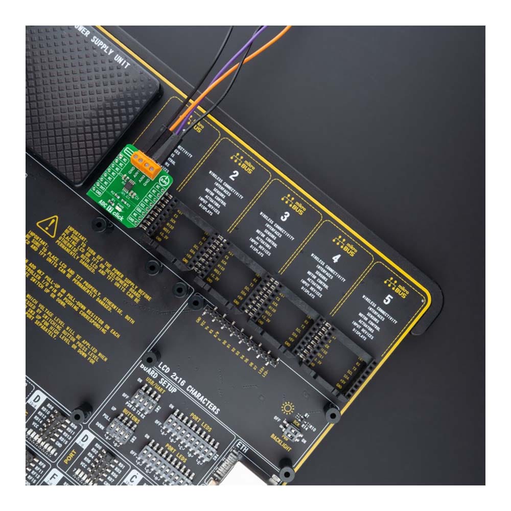
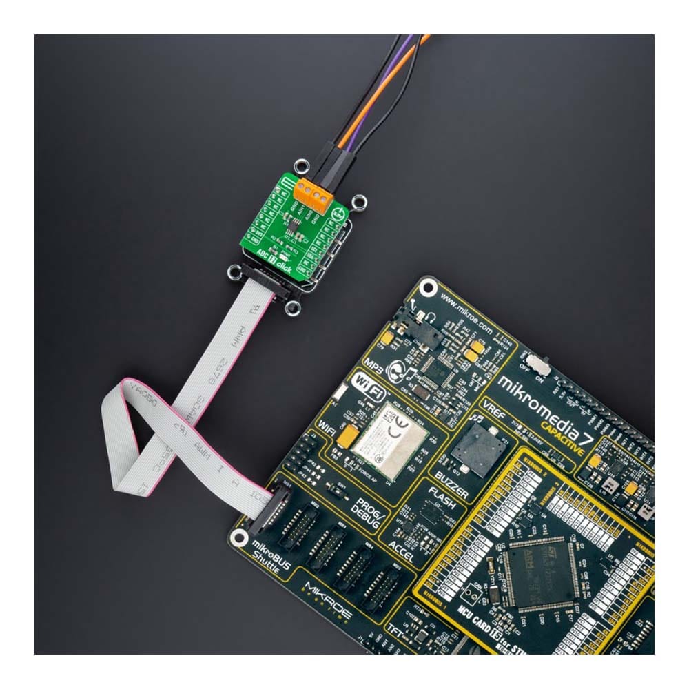
The ADC 17 Click Board™ is supported by a mikroSDK compliant library, which includes functions that simplify software development. This Click board™ comes as a fully tested product, ready to be used on a system equipped with the mikroBUS™ socket.
Downloads
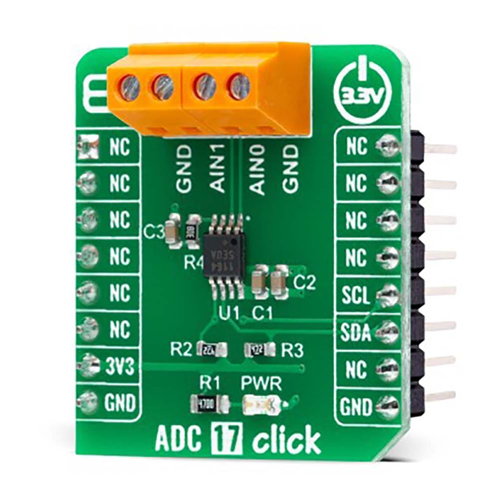
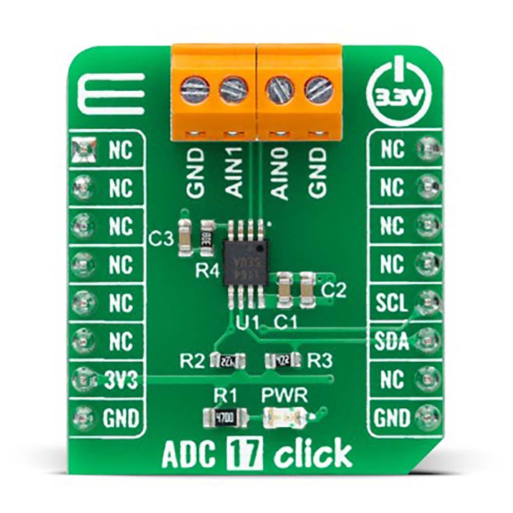
How Does The ADC 17 Click Board™ Work?
The ADC 17 Click Board™ as its foundation uses the MAX11645, a high-performance two-channel analog-to-digital converter (ADC) from Analog Devices. The MAX11645 uses successive-approximation conversion technique and fully differential input track/hold (T/H) circuitry to capture and convert an analog signal to a serial 12-bit digital output. It can measure either two single-ended or one differential input(s).
The MAX11645 is capable of sample rates up to 94ksps. By taking advantage of the ADC's high sample rate, multiple channels can be converted in a short period. This capability allows the device to spend more time in shutdown mode, reducing total power consumption. It also includes a 2.048V internal reference which determines its full-scale analog input range. The fully differential analog inputs are software configurable for unipolar or bipolar applications; input signals from 0 to VREF (unipolar) or ±VREF/2 (bipolar) range can be resolved with accurate 12-bit accuracy.
The ADC 17 Click Board™ communicates with MCU using the standard I2C 2-Wire interface to read data and configure settings, supporting Standard Mode operation with a clock frequency of 100kHz and Fast Mode up to 400kHz.
The ADC 17 Click Board™can be operated only with a 3.3V logic voltage level. The board must perform appropriate logic voltage level conversion before using MCUs with different logic levels. However, the Click board™ comes equipped with a library containing functions and an example code that can be used, as a reference, for further development.
SPECIFICATIONS
| Type | ADC |
| Applications | The ADC 17 Click Board™ be used for various applications from energy-harvesting sensors to portable consumer electronics, point-of-load monitoring (voltage, current, and temperature), and more |
| On-board modules | MAX11645 - high-performance two-channel analog-to-digital converter (ADC) from Analog Devices |
| Key Features | Two single-ended channels or one fully differential channel, low power consumption, high accuracy, software-configurable unipolar/bipolar operation, internal 2.048V reference, high-speed I2C interface, and more |
| Interface | I2C |
| Compatibility | mikroBUS |
| Click board size | S (28.6 x 25.4 mm) |
| Input Voltage | 3.3V |
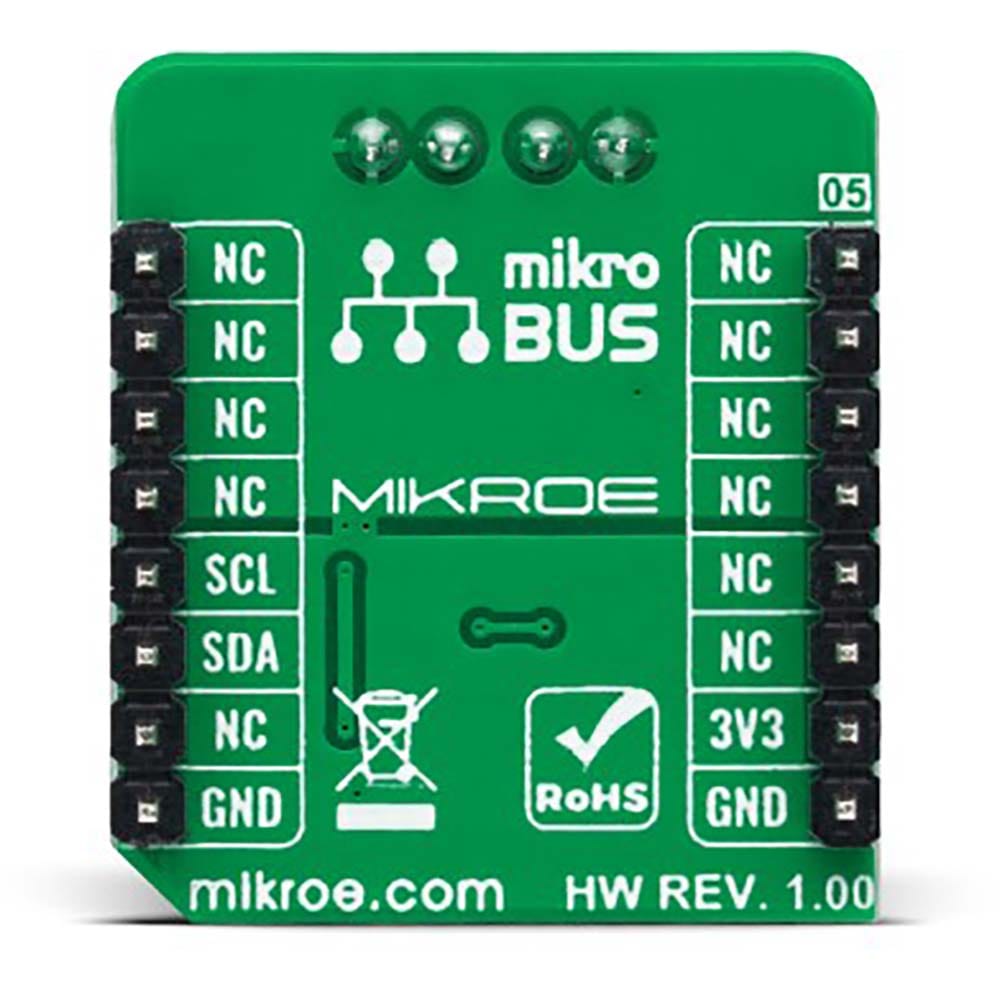
PINOUT DIAGRAM
This table shows how the pinout of the ADC 17 Click Board™ corresponds to the pinout on the mikroBUS™ socket (the latter shown in the two middle columns).
| Notes | Pin | Pin | Notes | ||||
|---|---|---|---|---|---|---|---|
| NC | 1 | AN | PWM | 16 | NC | ||
| NC | 2 | RST | INT | 15 | NC | ||
| NC | 3 | CS | RX | 14 | NC | ||
| NC | 4 | SCK | TX | 13 | NC | ||
| NC | 5 | MISO | SCL | 12 | SCL | I2C Clock | |
| NC | 6 | MOSI | SDA | 11 | SDA | I2C Data | |
| Power Supply | 3.3V | 7 | 3.3V | 5V | 10 | NC | |
| Ground | GND | 8 | GND | GND | 9 | GND | Ground |
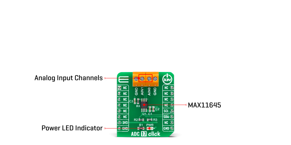
ONBOARD SETTINGS AND INDICATORS
| Label | Name | Default | Description |
|---|---|---|---|
| LD1 | PWR | - | Power LED Indicator |
ADC 17 CLICK ELECTRICAL SPECIFICATIONS
| Description | Min | Typ | Max | Unit |
|---|---|---|---|---|
| Supply Voltage | - | 3.3 | - | V |
| Analog Input Voltage | 0 | - | 2.048 | V |
| Resolution | - | 12 | - | bits |
| Operating Temperature Range | -40 | +25 | +30 | °C |
| General Information | |
|---|---|
Part Number (SKU) |
MIKROE-4966
|
Manufacturer |
|
| Physical and Mechanical | |
Weight |
0.02 kg
|
| Other | |
EAN |
8606027389467
|
Frequently Asked Questions
Have a Question?
Be the first to ask a question about this.