


Mikroelektronika d.o.o.
MUX 4 Click Board™
MUX 4 Click Board™
SKU: MIKROE-4754
Couldn't load pickup availability


Overview
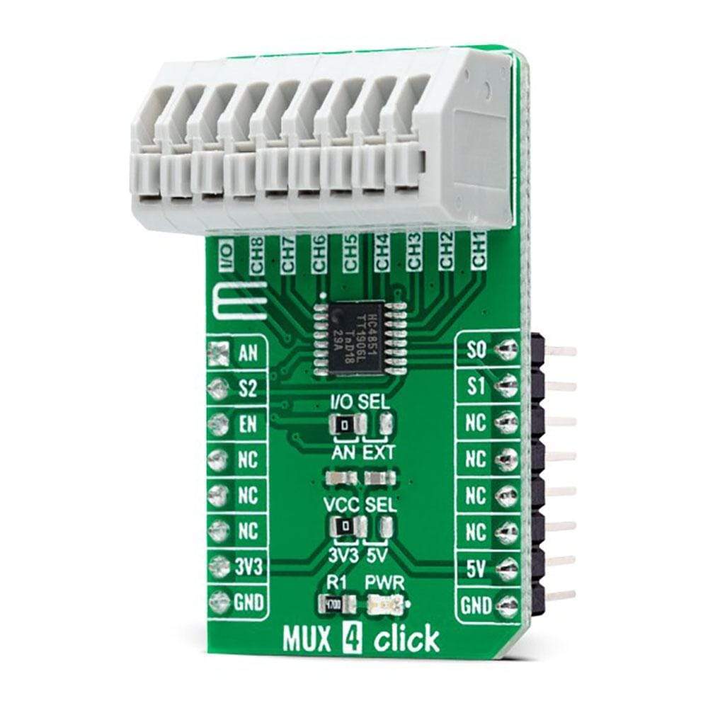
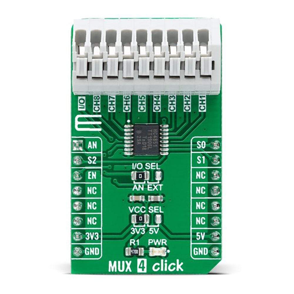
The MUX 4 Click Board™ is a compact add-on board that contains a precise analog multiplexing IC. This board features the 74HC4851, 8-channel analog multiplexer/demultiplexer with injection-current effect control from Nexperia USA Inc. This Click Board™ comes with three digital select inputs, active-LOW enable input, eight independent inputs/outputs, and a common input/output. It also features an injection-current effect control, which has excellent value in automotive applications where voltages above the supply voltage are common. This Click Board™ is suitable for a wide range of analog or digital mux/demux applications, from industrial and instrumentation, consumer, communications, and automotive systems.
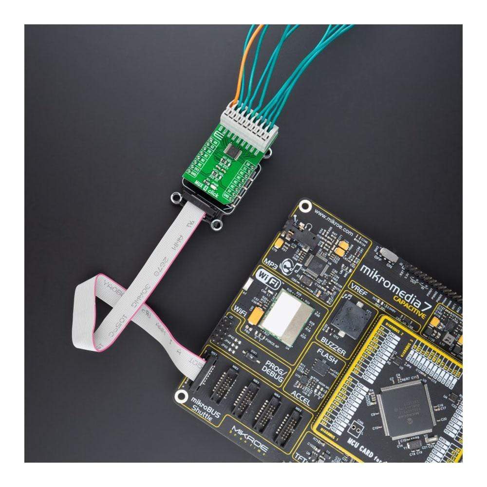
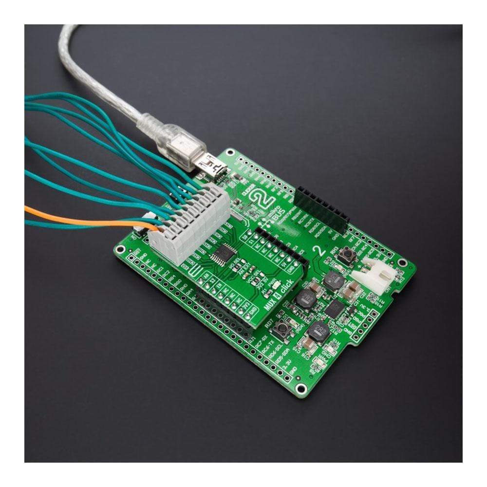
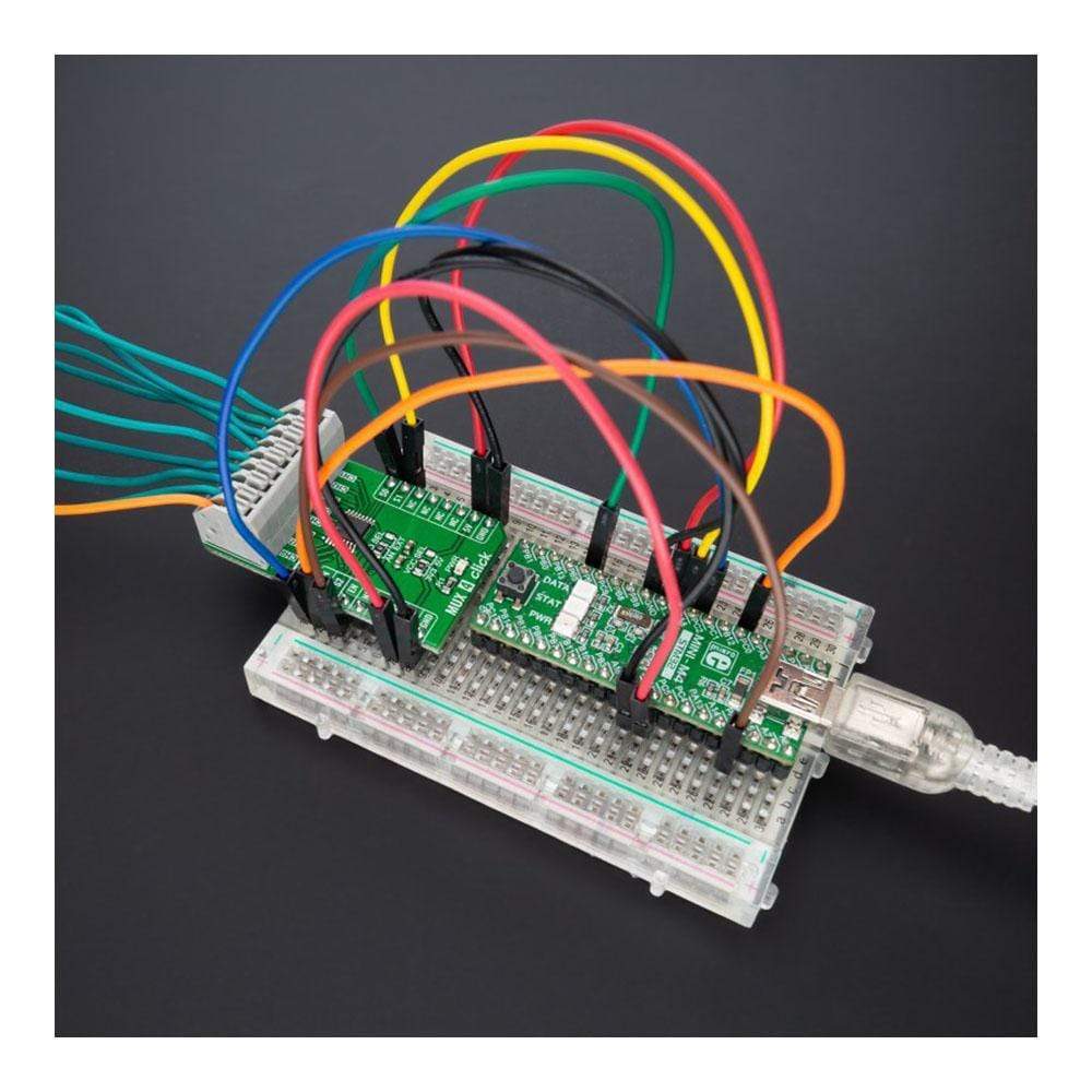
The MUX 4 Click Board™ is supported by a mikroSDK compliant library, which includes functions that simplify software development. This Click Board™ comes as a fully tested product, ready to be used on a system equipped with the mikroBUS™ socket.
Downloads
How Does The MUX 4 Click Board™ Work?
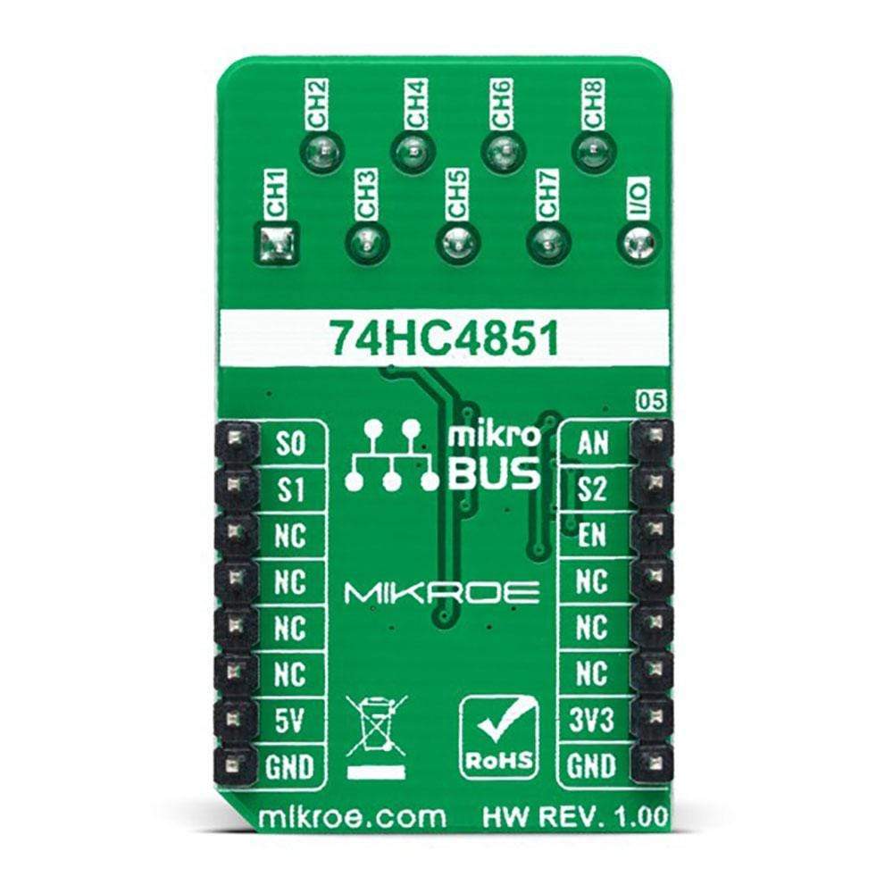
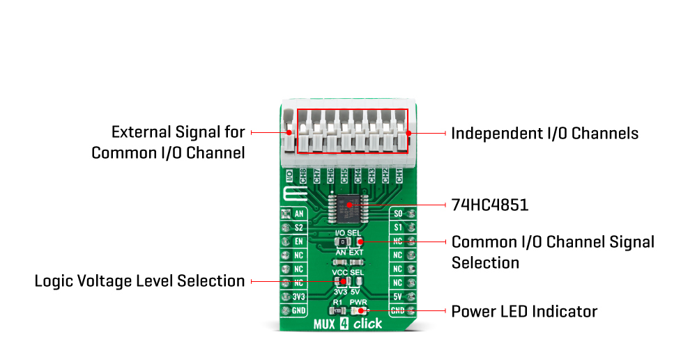
The MUX 4 Click Board™ as its foundation uses the 74HC4851, a precise 8-channel analog multiplexer/demultiplexer from Nexperia USA Inc. The 74HC4851 comes with eight independent input/output channels labeled from CH1 to CH8 that accept analog and digital signals of any voltage up to 5V. Compared to its predecessors, the 74HC4851 is better to use for the simple reason that it has a higher tolerance to a disturbance on channels that are not connected. Thanks to its characteristic of being both a multiplexer and a demultiplexer, the signals can travel in both directions.
The injection-current effect control, which is integrated inside the 74HC4851, allows signals at disabled analog input channels to exceed the supply voltage without affecting the signal of the enabled analog channel. This feature eliminates the need for external diode/resistor networks typically used to keep the analog channel signals within the supply-voltage range.
MUX 4 Click communicates with MCU using several GPIO pins. With EN pin, routed to the CS pin on the mikroBUS™ socket, is set to its low logic state, one of the eight switches is selected by three pins labeled as S0, S1, and S2 routed to the RST, PWM, and INT pins on the mikroBUS™ socket. With EN pin is set to its high logic state, all switches are in the high-impedance OFF-state, independent of S0 to S2 pins.
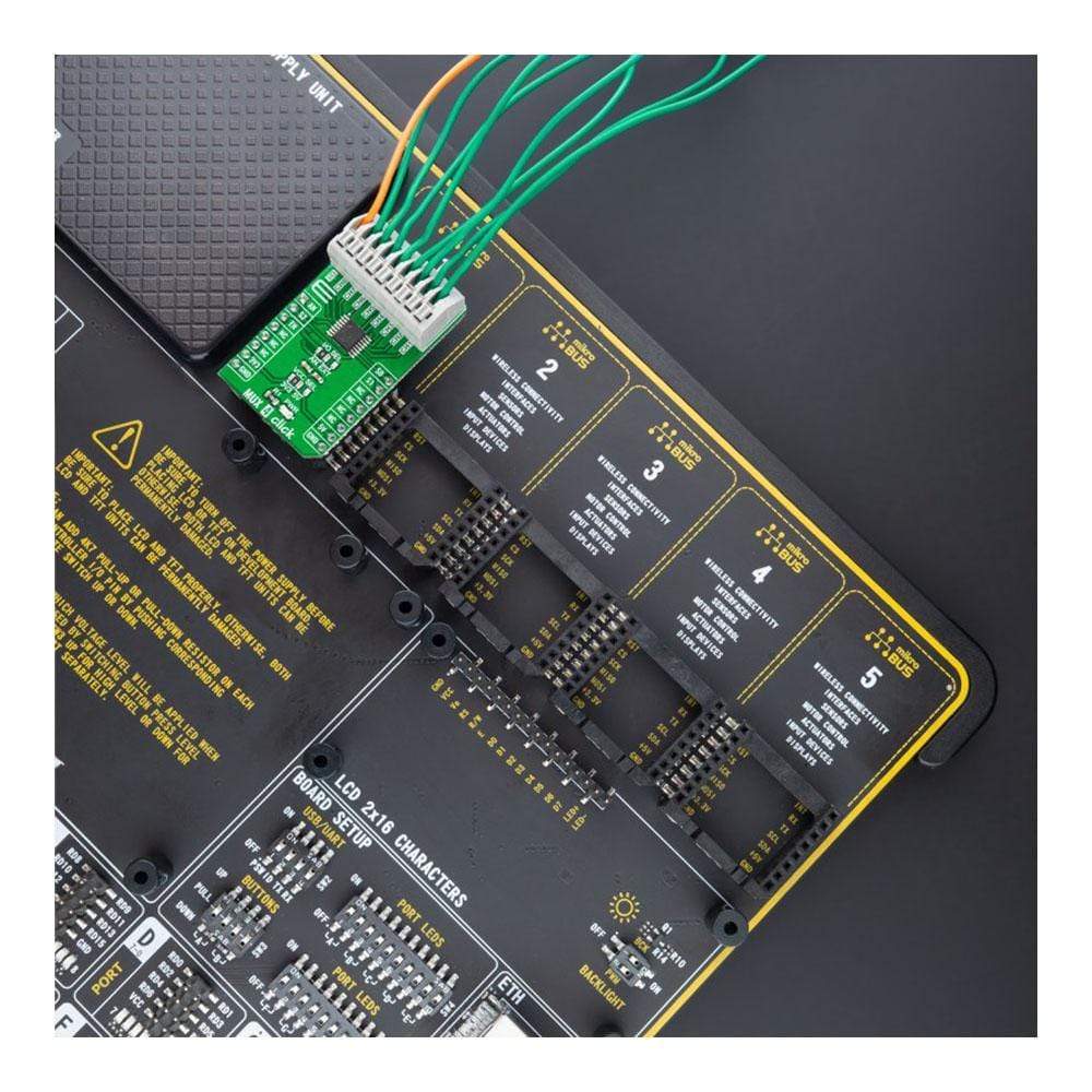
In addition to its eight independent input/output pins, the 74HC4851 also has a common input/output pin where it is possible to select the signal input to a given pin, more precisely, whether the signal will be brought externally from the terminal labeled as I/O or from mikroBUS™ socket AN pin. Selection can be performed by onboard SMD jumper labeled as I/O SEL to an appropriate position marked as AN and EXT. The MUX 4 Click comes equipped with one nine-position spring terminal for all input/output signals, making all wire connections reliable and straightforward.
The MUX 4 Click Board™ can operate with both 3.3V and 5V logic voltage levels selected via the VCC SEL jumper. This way, it allows both 3.3V and 5V capable MCUs to use the communication lines properly. However, the Click board™ comes equipped with a library containing easy-to-use functions and an example code that can be used, as a reference, for further development.
Specifications
| Type | DAC |
| Applications | Can be used for a wide range of analog or digital mux/demux applications, from industrial and instrumentation, consumer, communications, and automotive systems |
| On-board modules | 74HC4851 - precise 8-channel analog multiplexer/demultiplexer from Nexperia USA Inc |
| Key Features | Low power consumption, injection-current effect control, high speed, pin-controllable, eight channels, common I/O channel signal selection, and more |
| Interface | Analog,GPIO |
| Compatibility | mikroBUS |
| Click board size | M (42.9 x 25.4 mm) |
| Input Voltage | 3.3V or 5V |
Pinout diagram
This table shows how the pinout on MUX 4 Click corresponds to the pinout on the mikroBUS™ socket (the latter shown in the two middle columns).
| Notes | Pin | Pin | Notes | ||||
|---|---|---|---|---|---|---|---|
| Analog Signal | AN | 1 | AN | PWM | 16 | S0 | Channel Selection |
| Channel Selection | S2 | 2 | RST | INT | 15 | S1 | Channel Selection |
| Enable | EN | 3 | CS | RX | 14 | NC | |
| NC | 4 | SCK | TX | 13 | NC | ||
| NC | 5 | MISO | SCL | 12 | NC | ||
| NC | 6 | MOSI | SDA | 11 | NC | ||
| Power Supply | 3.3V | 7 | 3.3V | 5V | 10 | 5V | Power Supply |
| Ground | GND | 8 | GND | GND | 9 | GND | Ground |
Onboard settings and indicators
| Label | Name | Default | Description |
|---|---|---|---|
| LD1 | PWR | - | Power LED Indicator |
| JP1 | VCC SEL | Left | Logic Level Voltage Selection 3V3/5V: Left position 3V3, Right position 5V |
| JP2 | I/0 SEL | Left | Common I/O Channel Signal Selection AN/EXT: Left position AN, Right position EXT |
MUX 4 Click Electrical Specifications
| Description | Min | Typ | Max | Unit |
|---|---|---|---|---|
| Supply Voltage VCC | 3.3 | - | 5 | V |
| Input Voltage Range | 0 | - | VCC | V |
| ON Resistance (Peak) | - | - | 200 | Ω |
| Operating Temperature Range | -40 | +25 | +85 | °C |
| General Information | |
|---|---|
Part Number (SKU) |
MIKROE-4754
|
Manufacturer |
|
| Physical and Mechanical | |
Weight |
0.02 kg
|
| Other | |
EAN |
8606027383434
|
Frequently Asked Questions
Have a Question?
Be the first to ask a question about this.