


Mikroelektronika d.o.o.
DAC 10 Click Board™
DAC 10 Click Board™
SKU: MIKROE-4732
Couldn't load pickup availability


Key Features
Overview
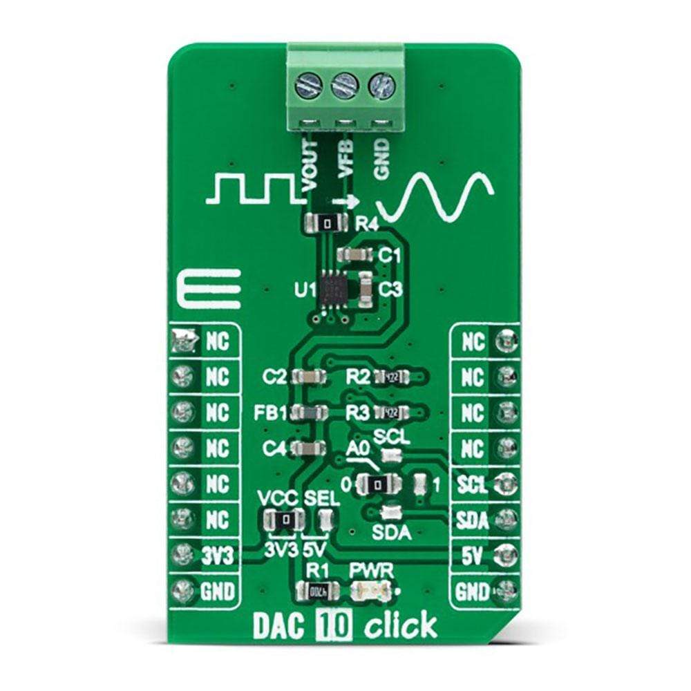
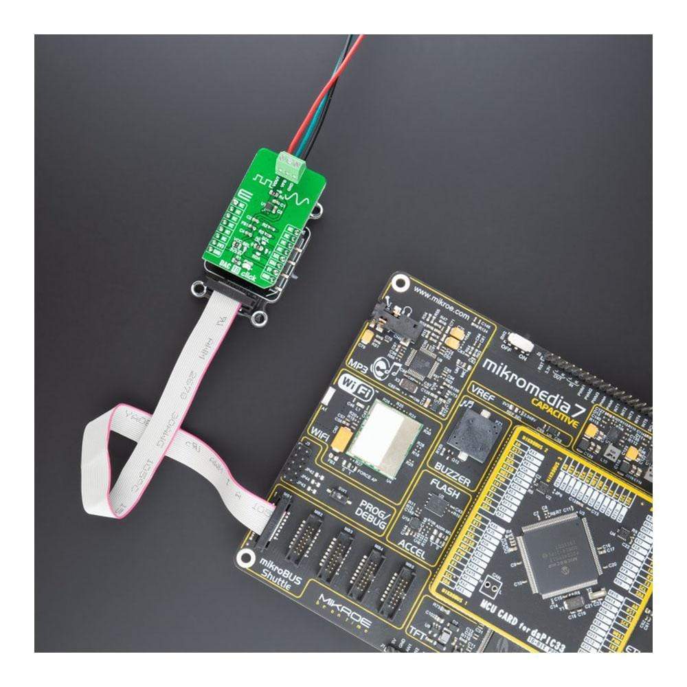
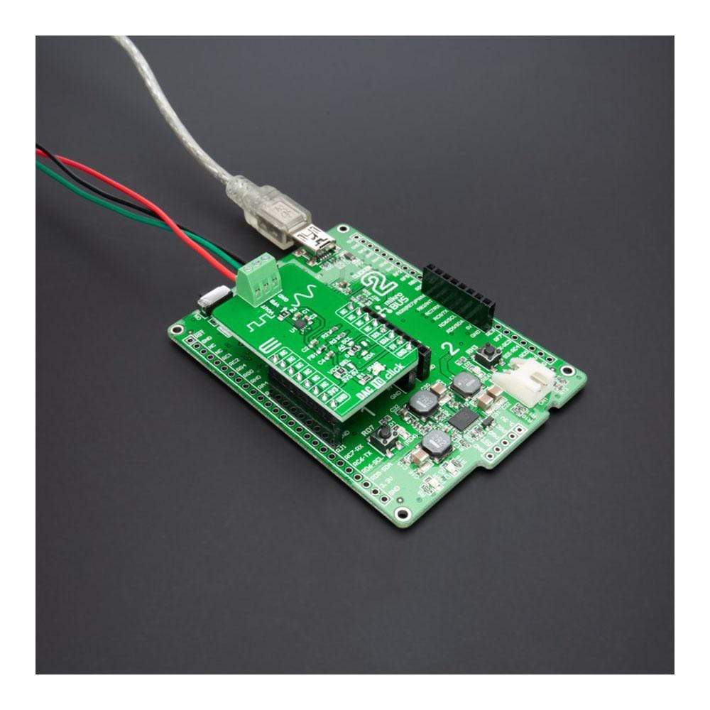
The DAC 10 Click Board™ is a compact add-on board that contains a fully-featured, highly accurate digital-to-analogue converter. This board features the DAC53401, a 10-bit voltage-output smart digital-to-analogue converter from Texas Instruments. This device consumes extremely low power and has a nonvolatile memory (NVM), an internal reference, and an I2C serial interface with a configurable slave address. It operates with either an internal reference or the power supply as a reference and provides full-scale output from 1.8V to 5.5V.
The DAC10 Click Board™ is a compact add-on board that contains a high-performance data converter that represents an excellent choice for applications such as LED and general-purpose bias point generation, power supply control, programmable reference, and more.
Downloads
How Does The DAC 10 Click Board™ work?
The DAC 10 Click Board™ as its foundation uses the DAC53401, a 10-bit voltage-output smart digital-to-analog converter from Texas Instruments. This device consumes extremely low power and has a non-volatile memory (NVM), an internal reference, and an I2C serial interface. It also has a power-on-reset circuit that makes sure all the registers start with default or user-programmed settings using NVM. It operates with either an internal reference or the power supply as a reference and provides full-scale output from 0V to 5.5V.

The DAC53401 includes digital slew rate control and supports basic signal generation such as square, ramp, and sawtooth waveforms. It also can generate pulse-width modulation (PWM) output with the combination of the triangular or sawtooth waveform and the VFB terminal. The DAC53401 is also called a smart DAC device because of its advanced integrated features. The force-sense output, PWM output, and NVM capabilities of this smart DAC enable system performance and control without using the software. These features allow DAC53401 to go beyond a conventional DAC's limitations that depend on a processor to function.
The DAC 10 Click Board™ communicates with MCU using the standard I2C 2-Wire interface to read data and configure settings, supporting Standard Mode operation with a clock frequency up to 100kHz, Fast Mode up to 400kHz, and Fast Mode Plus up to 1MHz. Besides, it also allows the choice of the three least significant bits of its I2C slave address by positioning the SMD jumper labeled as ADDR SEL to an appropriate position marked as 0, 1, SCL, and SDA, providing the user with a choice of 4 I2C Slave addresses.
The DAC 10 Click Board™ can operate with both 3.3V and 5V logic voltage levels selected via the VCC SEL jumper. This way, it is allowed for both 3.3V and 5V capable MCUs to use the I2C communication lines properly. However, the Click board™ comes equipped with a library containing easy-to-use functions and an example code that can be used, as a reference, for further development.
SPECIFICATIONS
| Type | DAC |
| Applications | Can be used for applications such as LED and general-purpose bias point generation, power supply control, programmable reference, and more |
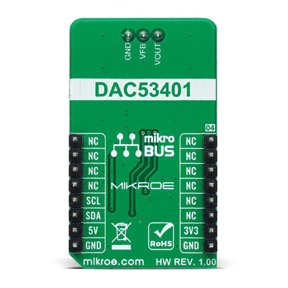
| On-board modules | DAC53401 - 10-bit voltage-output smart digital-to-analog converter from Texas Instruments |
| Key Features | Low power consumption, voltage-output smart DAC, user-programmable nonvolatile memory, I2C compatible interface, programmable waveform generation, PWM output using triangular waveform and VFB terminal, and more |
| Interface | I2C |
| Compatibility | mikroBUS |
| Click board size | M (42.9 x 25.4 mm) |
| Input Voltage | 3.3V or 5V |
PINOUT DIAGRAM
This table shows how the pinout on DAC 10 Click corresponds to the pinout on the mikroBUS™ socket (the latter shown in the two middle columns).
| Notes | Pin | Pin | Notes | ||||
|---|---|---|---|---|---|---|---|
| NC | 1 | AN | PWM | 16 | NC | ||
| NC | 2 | RST | INT | 15 | NC | ||
| NC | 3 | CS | RX | 14 | NC | ||
| NC | 4 | SCK | TX | 13 | NC | ||
| NC | 5 | MISO | SCL | 12 | SCL | I2C Clock | |
| NC | 6 | MOSI | SDA | 11 | SDA | I2C Data | |
| Power Supply | 3.3V | 7 | 3.3V | 5V | 10 | 5V | Power Supply |
| Ground | GND | 8 | GND | GND | 9 | GND | Ground |
ONBOARD SETTINGS AND INDICATORS
| Label | Name | Default | Description |
|---|---|---|---|
| LD1 | PWR | - | Power LED Indicator |
| JP1 | VCC SEL | Left | Logic Level Voltage Selection 3V3/5V: Left position 3V3, Right position 5V |
| JP2-JP3 | ADDR SEL | Left | I2C Address Selection 0/1/SCL/SDA: Left position 0, Right position 1, Upper position SCL, Lower position SDA |
DAC 10 CLICK ELECTRICAL SPECIFICATIONS
| Description | Min | Typ | Max | Unit |
|---|---|---|---|---|
| Supply Voltage | 3.3 | - | 5 | V |
| Output Voltage Range | 0 | - | 5.5 | V |
| Resolution | - | 10 | - | bits |
| Operating Temperature Range | -40 | +25 | +125 | °C |
| General Information | |
|---|---|
Part Number (SKU) |
MIKROE-4732
|
Manufacturer |
|
| Physical and Mechanical | |
Weight |
0.02 kg
|
| Other | |
EAN |
8606027383267
|
Frequently Asked Questions
Have a Question?
Be the first to ask a question about this.