


Mikroelektronika d.o.o.
Expand 8 Click Board™
Expand 8 Click Board™
SKU: MIKROE-4442
Couldn't load pickup availability
Key Features
Overview
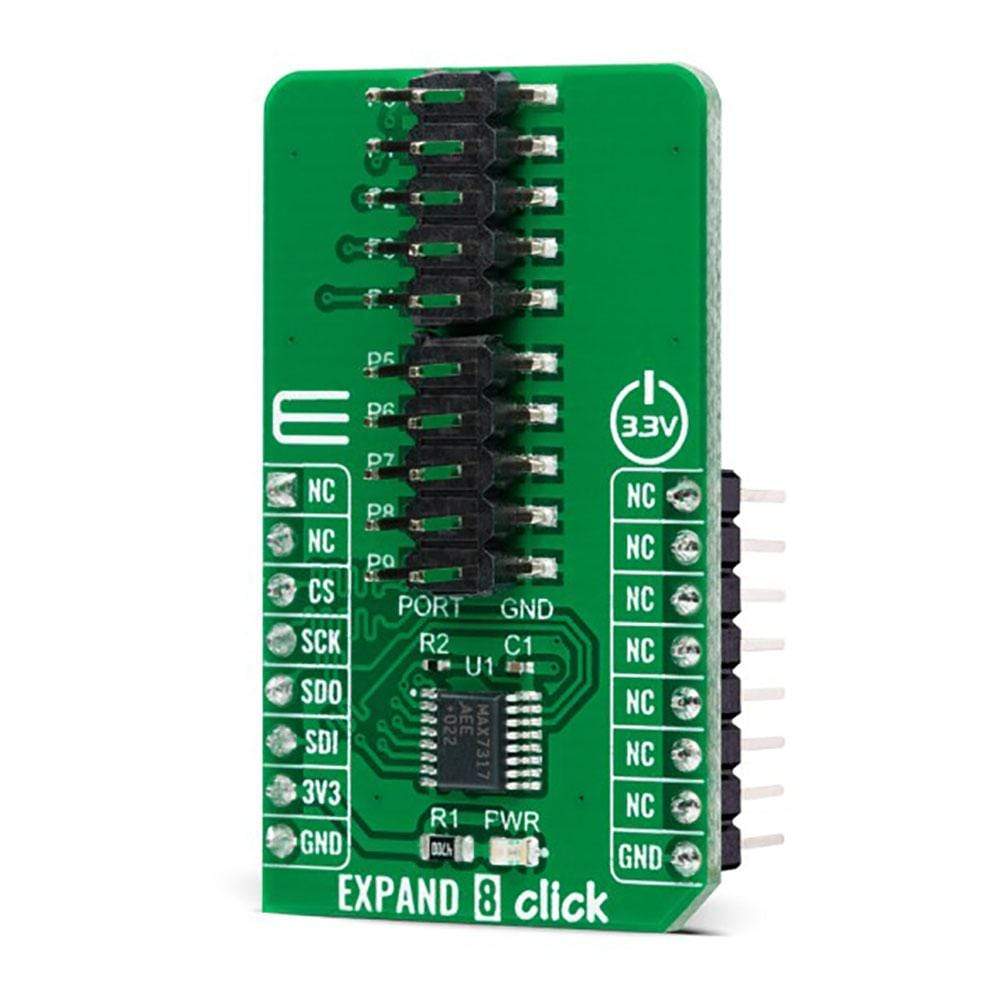
The Expand 8 Click Board™ is a compact add-on board that contains a multi-port I/O expander with bi-directional input/outputs. This board features the MAX7317, 10-Port SPI-interfaced I/O expander with overvoltage and hot-insertion protection from Maxim Integrated. The MAX7317 provides microprocessors with 10 I/O ports rated to 7V. Each port can be individually configured as either an open-drain output or an overvoltage-protected Schmitt input that supports hot insertion. All port pins remain high impedance in Power-Down mode with up to 8V asserted on them. This Click Board™ is intended for use as a port expander in system monitoring applications, industrial controllers, portable equipment, and many more.
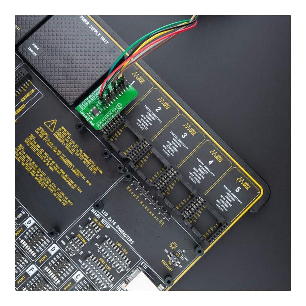
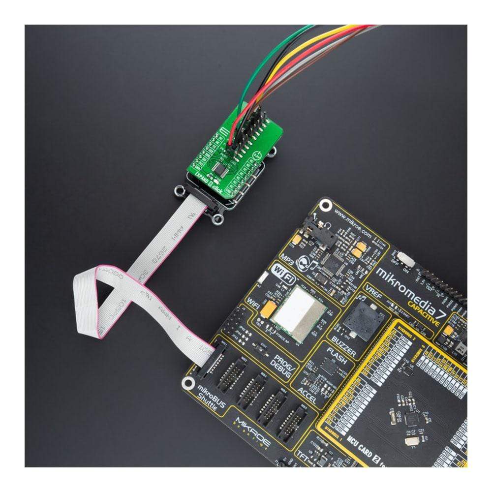
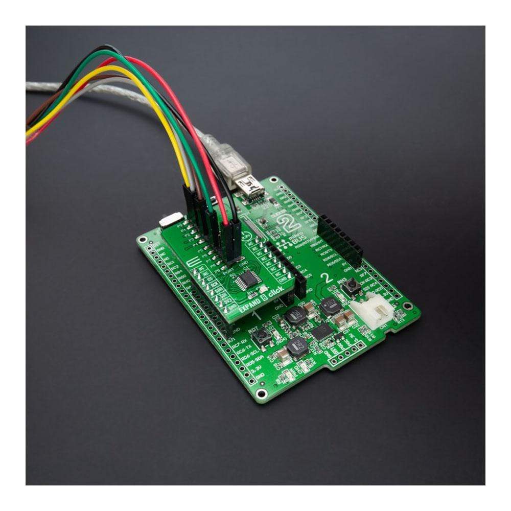
Expand 8 Click is supported by a mikroSDK compliant library, which includes functions that simplify software development. This Click Board™ comes as a fully tested product, ready to be used on a system equipped with the mikroBUS™ socket.
Downloads
How Does the Expand 8 Click Board™ work?
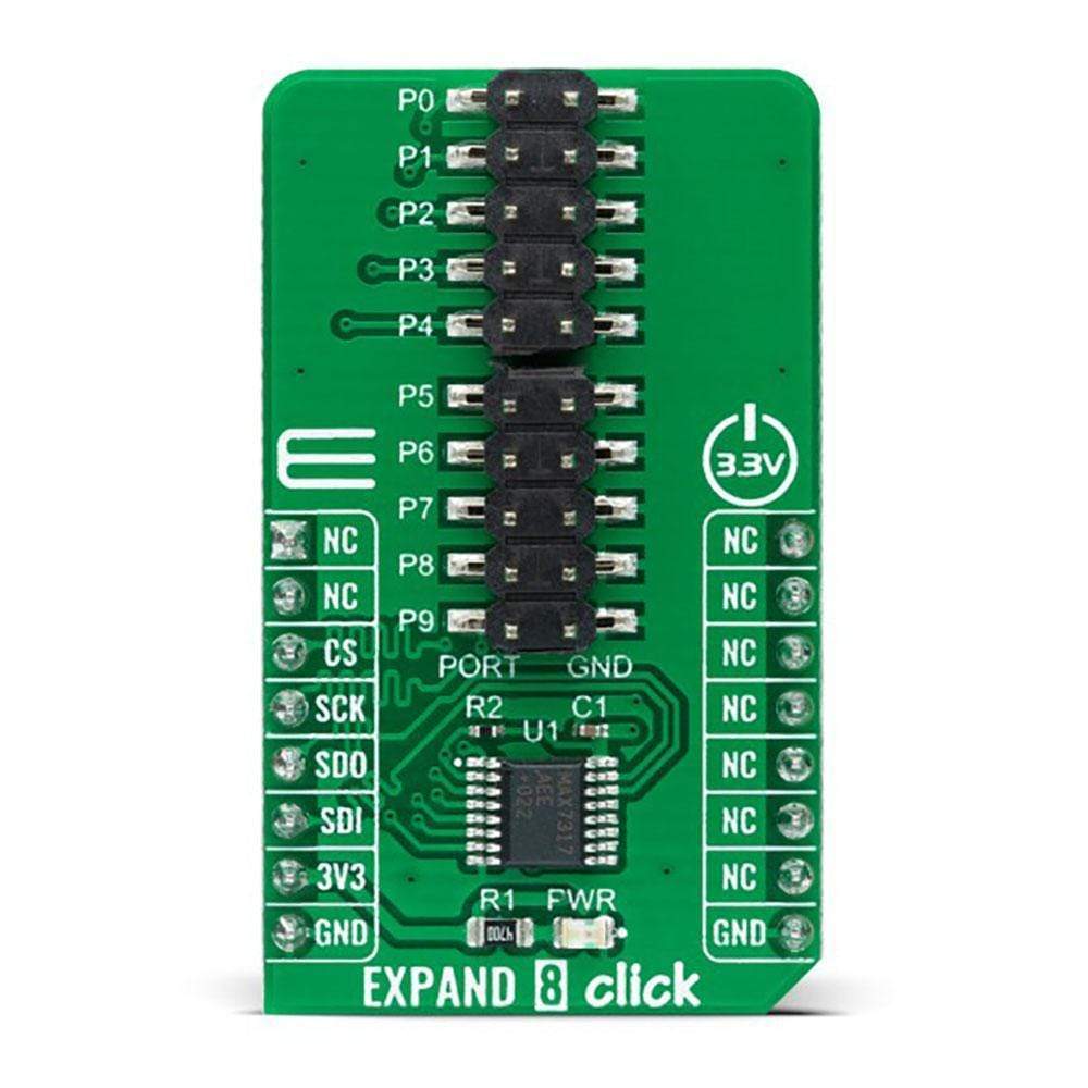
The Expand 8 Click Board™ as its foundation uses the MAX7317, a general-purpose input/output (GPIO) peripheral from Maxim Integrated that provides 10 I/O ports, P0 to P9, controlled through a high-speed SPI-compatible serial interface. Each port, P0 to P9 can be configured as open-drain, current-sink outputs rated at 20mA maximum, or as CMOS inputs, or as open-drain outputs. Loads should be connected to a supply voltage no higher than 7V.

The MAX7317 contains ten 8-bit internal registers. These ten registers are addressed as 0x00 - 0x09 control an I/O port each. Write 0x00 to the output register to set the port as a logic-low output, or 0x01 to set the port as a logic-high output or logic input.
Expand 8 Click communicates with MCU through a 16-bit 4-wire serial interface compatible with standard SPI, QSPI™, MICROWIRE™ guaranteed to operate at 35Mbps on its 3.3V power supply. During the Power-Up sequence, all control registers of the MAX7317 are in a reset state. Power-Up status sets I/O ports, P0 to P9, into a high impedance state and puts the device into Shutdown mode. The I/O ports P0–P9 remains high impedance with up to 8V asserted on them when the MAX7317 is powered down. Therefore, it can be used in hot-swap applications.
This Click board™ can be operated only with a 3.3V logic voltage level. The board must perform appropriate logic voltage level conversion before use with MCUs with different logic levels. However, the Click board™ comes equipped with a library containing functions and an example code that can be used, as a reference, for further development.
SPECIFICATIONS
| Type | Port expander |
| Applications | Intended for use as a port expander in system monitoring applications, industrial controllers, portable equipment, and many more. |
| On-board modules | MAX7317 - 10-Port SPI-interfaced I/O expander with overvoltage and hot-insertion protection from Maxim Integrated |
| Key Features | 10-Port I/O expander, overvoltage protection, support hot-insertion, SPI, QSPI™, MICROWIRE™ compatible serial interface, low power consumption, and more. |
| Interface | SPI |
| Compatibility | mikroBUS |
| Click board size | M (42.9 x 25.4 mm) |
| Input Voltage | 3.3V |
PINOUT DIAGRAM
This table shows how the pinout on Expand 8 Click corresponds to the pinout on the mikroBUS™ socket (the latter shown in the two middle columns).
| Notes | Pin | Pin | Notes | ||||
|---|---|---|---|---|---|---|---|
| NC | 1 | AN | PWM | 16 | NC | ||
| NC | 2 | RST | INT | 15 | NC | ||
| SPI Chip Select | CS | 3 | CS | RX | 14 | NC | |
| SPI Clock | SCK | 4 | SCK | TX | 13 | NC | |
| SPI Data OUT | SDO | 5 | MISO | SCL | 12 | NC | |
| SPI Data IN | SDI | 6 | MOSI | SDA | 11 | NC | |
| Power Supply | 3.3V | 7 | 3.3V | 5V | 10 | NC | |
| Ground | GND | 8 | GND | GND | 9 | GND | Ground |
ONBOARD SETTINGS AND INDICATORS
| Label | Name | Default | Description |
|---|---|---|---|
| LD1 | PWR | - | Power LED Indicator |
| J1-J2 | P0-P9 | Populated | I/O Expander Port |
EXPAND 8 CLICK ELECTRICAL SPECIFICATIONS
| Description | Min | Typ | Max | Unit |
|---|---|---|---|---|
| Supply Voltage | - | 3.3 | - | V |
| Output Load Voltage P0 - P9 | - | - | 7 | V |
| Maximum Output Current | - | - | 20 | mA |
| Operating Temperature Range | -40 | +25 | +125 | °C |
| General Information | |
|---|---|
Part Number (SKU) |
MIKROE-4442
|
Manufacturer |
|
| Physical and Mechanical | |
Weight |
0.02 kg
|
| Other | |
EAN |
8606027382659
|
Frequently Asked Questions
Have a Question?
Be the first to ask a question about this.