


Mikroelektronika d.o.o.
ADC 12 Click Board™
ADC 12 Click Board™
SKU: MIKROE-4376
Couldn't load pickup availability


Key Features
Overview
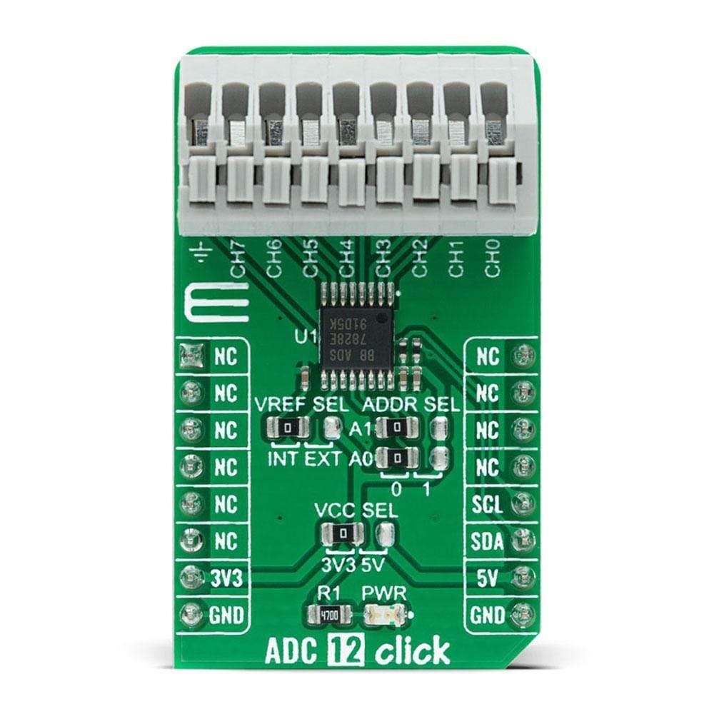
The ADC 12 Click Board™ is a compact add-on board that contains a fully-featured, general-purpose analogue-to-digital converter. This board features the ADS7828, a low-power 12-bit data acquisition device that features a serial I2C interface and an 8-channel multiplexer from Texas Instruments. The A/D converter features a sample-and-hold amplifier and an internal, asynchronous clock. The combination of an I2C serial interface, up to eight differential analogue inputs, built-in reference with buffered output, and micro-power consumption makes this Click Board™ ideal for applications requiring the A/D converter to be close to the input source in remote locations and for applications requiring isolation.
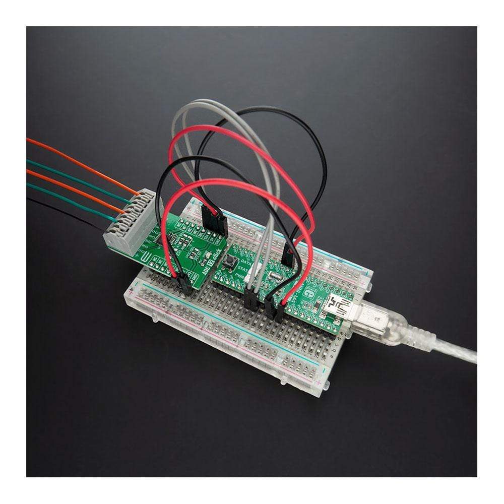
The ADC 12 Click Board™ is supported by a mikroSDK compliant library, which includes functions that simplify software development. This Click Board™ comes as a fully tested product, ready to be used on a system equipped with the mikroBUS™ socket.
Downloads
How Does The ADC 12 Click Board™ Work?
The ADC 12 Click Board™ is based on the ADS7828, a low-power 12-bit data acquisition device that features a serial I2C interface and an 8-channel multiplexer from Texas Instruments. The architecture of the ADS7828, which is a classic Successive Approximation Register (SAR) A/D converter, is based on capacitive redistribution that inherently includes a sample-and-hold function. It has an integrated I2C input and output port as well as screw terminal connectors for each analogue input channel. It is controlled by an internally generated free-running clock. When the ADS7828 is not performing conversions or being addressed, it keeps the A/D converter core powered off, and the internal clock does not operate.
When the A/D converter enters the Hold mode, the voltage on the selected channel pin of the input terminal is captured on the internal capacitor array. The input current on the analogue inputs depends on the conversion rate of the device. During the sample period, the source must charge the internal sampling capacitor. After the capacitor has been fully charged, there is no further input current. The amount of charge transfer from the analogue source to the converter is a function of the conversion rate.
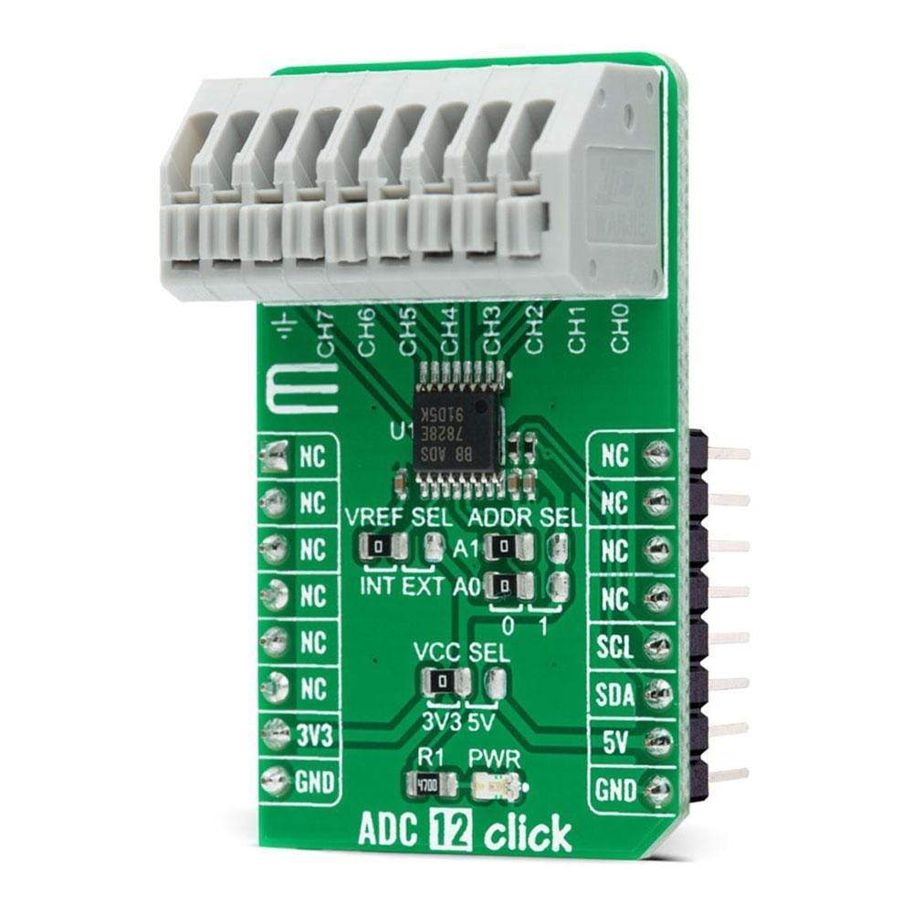
The ADC 12 Click Board™ communicates with MCU using the standard I2C 2-Wire interface with a frequency up to 100kHz in the Standard, up to 400kHz in the Fast, and up to 3.4MHz in the High-Speed mode. It also allows the choice of the last two least significant bits (LSB) A0 and A1 by positioning SMD jumpers labelled as ADDR SEL to an appropriate position marked as 0 and 1. This Click board™ also posses a jumper for selecting the reference voltage labelled as VREF SEL. The ADS7828 can operate with an internal 2.5V reference or an external reference (in this case logic voltage level VCC), which can be selected by positioning SMD jumpers to an appropriate position marked as INT and EXT.
The ADC 12 Click Board™ is designed to be operated with both 3.3V and 5V logic voltage levels that can be selected via VCC SEL jumper. This allows for both 3.3V and 5V capable MCUs to use the I2C communication lines properly. However, the Click board™ comes equipped with a library that contains easy to use functions and an example code that can be used as a reference for further development.
Specifications
| Type | ADC |
| Applications | Can be used for applications requiring the A/D converter to be close to the input source in remote locations and for applications requiring isolation. |
| On-board modules | ADC 12 Click is based on the ADS7828, a low-power 12-bit data acquisition device that features a serial I2C interface and an 8-channel multiplexer from Texas Instruments. |
| Key Features | Low power consumption, 12-bit data acquisition device, 8-channel multiplexer, internal voltage reference, and more. |
| Interface | I2C |
| Compatibility | mikroBUS |
| Click board size | M (42.9 x 25.4 mm) |
| Input Voltage | 3.3V or 5V |
Pinout diagram
This table shows how the pinout on the ADC 12 Click Board™ corresponds to the pinout on the mikroBUS™ socket (the latter shown in the two middle columns).
| Notes | Pin | Pin | Notes | ||||
|---|---|---|---|---|---|---|---|
| NC | 1 | AN | PWM | 16 | NC | ||
| NC | 2 | RST | INT | 15 | NC | ||
| NC | 3 | CS | RX | 14 | NC | ||
| NC | 4 | SCK | TX | 13 | NC | ||
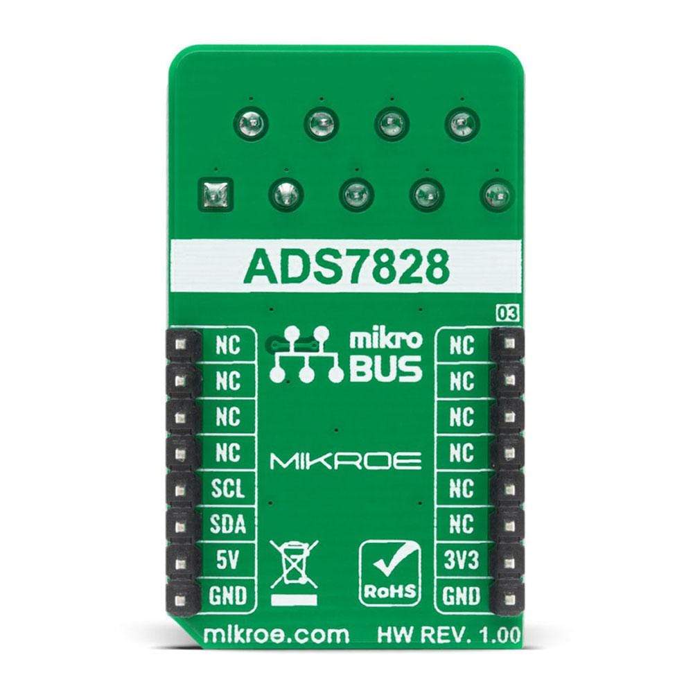
| NC | 5 | MISO | SCL | 12 | SCL | I2C Clock | |
| NC | 6 | MOSI | SDA | 11 | SDA | I2C Data | |
| Power Supply | 3.3V | 7 | 3.3V | 5V | 10 | 5V | Power Supply |
| Ground | GND | 8 | GND | GND | 9 | GND | Ground |
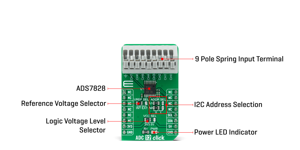
Onboard settings and indicators
| Label | Name | Default | Description |
|---|---|---|---|
| LD1 | PWR | - | Power LED Indicator |
| JP1 | VCC SEL | Left | Power Supply Voltage Selection 3V3/5V: Left position 3V3, Right position 5V |
| JP2 | VREF SEL | Left | Reference Voltage Selection INT/EXT: Left position INT, Right position EXT |
| JP3-JP4 | ADDR SEL | Left | I2C Address Selection: Left position 0, Right position 1 |
ADC 12 Click electrical specifications
| Description | Min | Typ | Max | Unit |
|---|---|---|---|---|
| VCC Supply Voltage | -0.3 | - | 6 | V |
| ADC Supply Voltage | 0 | - | 5.25 | A |
| Power Consumption | - | - | 0.68 | mW |
| Operating Temperature Range | -40 | - | +85 | °C |
| General Information | |
|---|---|
Part Number (SKU) |
MIKROE-4376
|
Manufacturer |
|
| Physical and Mechanical | |
Weight |
0.027 kg
|
| Other | |
EAN |
8606027381058
|
Frequently Asked Questions
Have a Question?
Be the first to ask a question about this.